

- 11 -
18.
In its factory default setting, the radiant element will
be allowed to operate for up to 2 hours after the beginning of
the off peak charge period to maintain a comfortable room
temperature if required. After 2 hours the radiant element
will be automatically disabled until the end of the off peak
charge period.
In circumstances where it will not be necessary to maintain
a high ambient room temperature between the hours
of typically 12am and 2am (for example a commercial
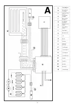
application) this feature can be disabled by removing the
time delay pin on the power enable board (see Fig. 18
A
),
which will automatically switch the radiant element off at
the beginning of the off peak charge period.
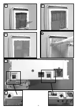
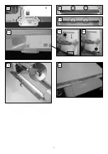
RADIANT ELEMENT OVERRIDE
REASSEMBLY
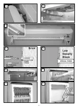
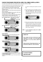
19. Reconnect the radiant element connector as shown
in Fig 19
A
-19
H
. Replace the outer front panel by hooking
onto the two location clips on the top panel Fig. 19
B
, 19
C
& 19
E
. Swing the bottom of the front panel gently towards
the radiator Fig. 19
F
until the radiant element connector is
securely placed at the base of the radiator Fig. 19
D
.
Hook
slots at the bottom of the plinth over the plinth fi xing tabs on
the plastic feet, as shown in Fig. 19
G
. Slide the plinth into
place as shown in Fig. 19
H
a
nd secure in place.
ON NO ACCOUNT SHOULD ANY SURPLUS CABLE
BE PUSHED INSIDE OR BEHIND THE RADIATOR.
CHECK ALL ELECTRICAL CONNECTIONS FOR
TIGHTNESS.
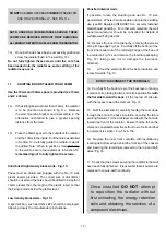
IMPORTANT
20. The wires in the direct acting supply cable are coloured
in accordance with the following code:
GREEN & YELLOW: EARTH
BLUE: NEUTRAL
BROWN: LIVE
BLACK: PILOT WIRE
ELECTRICAL CONNECTION
The BLACK pilot wire is designed to carry a signal from
a compatible remote programming device. If, however, a
remote programmer is not being used, the appliance may
be connected to the
fi
xed wiring of the premises simply by
cutting back the BLACK pilot wire, ensuring that it terminates
within the outer insulating sheath of the supply cable.
DO NOT
connect the BLACK PILOT WIRE to earth. When
the programmer drives other radiators, connect the pilot
wires together in series. Any 240V insulated cable may be
used to link pilot wires around the ring main. A low signal
current is used. Suitable connections would be either
an additional single core wire marked or colour coded
appropriately or use a 4 core cable throughout the radiator
ring. As a mains conductor, the pilot wire should be isolated
in accordance with the IEE regulations.
For further details of connection to programming devices,
please refer to the relevant programmer instructions.
The ability to ‘lock’ the controls eg. school conditions, is
achieved by removing the pin shown in Fig. 18
B
, which will
prevent appliance settings being altered.
REPLACING MAINS WIRE ON DIRECT ACTING
SUPPLY CIRCUIT
HEAT RESISTING CABLE MUST BE USED
(MIN. T85)


