background image

- 12 -

2. 

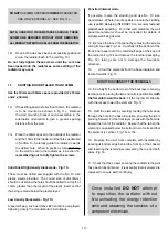
To check the radiant panel operation (comfort 
heat).

(i)  Adjust the temperature control display as follows; 

press down the 

+


button until all red bars are 

illuminated (shown below).  After 2 minutes the 
front panel should now feel warm, this will con

fi

 rm 

correct operation.  

(ii) If  the front panel does not heat up and room 

temperature is below 26°C, remove front panel 
and ensure there is no damage to front panel or 
radiant element and that all electrical connections 
are secure.  If front panel is still not heating up, 
phone customer help line.

NOTE:  If room temperature is above 26°C, radiator 

will not operate.

I

MPORTANT

Once radiator has been con

fi

 rmed as fully 

operational, use Page 2 of the ‘Operating 
Instructions’ to set up initial customer 
settings.

Please ensure the “Operating Instructions” are 
left with the radiator for user information.

Eco Response has a built in self diagnostic function that enables 
both service engineers and end users to diagnose faults.
Make sure that the peak supply is on before starting the 
diagnostic function.
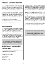
Adjust the LED’s down until only the blue frost protection 
LED is illuminated.
Press and hold the  

-


button for 10 seconds until the blue 

LED goes off then release the 

-


button.

The LED’s will now come on one at a time - this indicates 
that the radiator is running the diagnostic checks.

fl

 ashing LED will then illuminate to indicate a pass or fail.

Pass - 8th LED 

fl

 ashes -  

if Wall Mounted Programmer 


    (PWE4ZC) is not 

                                                connected or in Comfort Mode.

Pass - 9th LED 

fl

 ashes -  

if Wall Mounted Programmer 


(PWE4ZC) 

is 

in 

Setback           

                                                  mode.

Fault Conditions

1st Red LED 

fl

 ashing - Room temperature sensor fault.

2nd Red LED 

fl

 ashing - Core temperature sensor fault.

3rd Red LED 

fl

 ashing - Radiant Panel temperature fault.

Contact Customer Helpline if any of the above faults are 
detected.

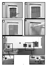
CHECK PROCEDURE FOR INSTALLERS FOLLOWING INSTALLATION

THIS CHECK PROCEDURE SHOULD BE CARRIED OUR BY A COMPETENT INSTALLER 

ONLY

.  

THE OPERATING INSTRUCTIONS ARE AVAILABLE FOR END USERS.

To exit diagnostic mode press either 

or 

to return 

to normal running mode.

Customer Helpline
0845 604 2399

Summary of Contents for 75773301

Page 1: ... 1 ER300 75773301 1 3kW 0 38kW 9 1kWh ER400 75773302 1 95kW 0 47kW 13 65kWh ER500 75773303 2 6kW 0 54kW 18 2kWh 87956 Issue 3 April 2010 Installation Instructions Storage Radiant Heaters ...

Page 2: ...G Core Sensing Thermistor H Charge Controller Module I User Interface Module J Peak Supply K Radiant Element L Live N Neutral P Pilot Wire E Manual Fit Connector L1 Live Storage In L2 Live Storage Out L3 Live Radiant In L4 Live Radiant Out S1 Signal In S2 Signal Out N1 Neutral In N2 Neutral Out M Off Peak Supply ER300 ER400 ER500 ...

Page 3: ...struction 110mm 150mm min 250mm min 75mm min 75mm min A B C Model Height Width Depth ER300 75773301 712mm 600mm 130mm 10mm ER400 75773302 712mm 830mm 130mm 10mm ER500 75773303 712mm 1060mm 130mm 10mm Dimensions including clearances diagram millimetres A B C ...

Page 4: ... 4 2 1 6 4 1 2 10mm 10A 10B 2 1 2 2 2 5 ...

Page 5: ... 5 30mm 10E 10F 11A 11c 11D 12A 12B 12C 13 ...

Page 6: ... 6 16 14 15A 15B 18B 18 18A ...

Page 7: ... 7 2 1 19A 19B 19C 19E 19F 19D 19G 19H ...

Page 8: ... For other wall types seek specialist advice WARNING If during any reassembly of the radiator a part of the thermal insulation shows damage or deterioration which may impair safety it should be replaced with an identical part WARNING This radiator must not be located below a fixed socket outlet WARNING in order to avoid overheating do not cover the radiator DO NOT COVER OR OBSTRUCT the surfaces of...

Page 9: ...r ensuring it is secure during transit The off peak mains cable will be secured with clips Prior to installing the radiator unclip the direct acting mains cable do not remove or discard these clips NOTE If the off peak mains connection is required to be made on the right hand side of the radiator the pre wired cable must be passed behind the feet and secured using the clips on the base of the radi...

Page 10: ...g the screws along its top edge Fig 12A Carefully lift the bottom of the front inner panel out of the retaining flange at the base of the radiator Fig 12B and remove the internal packaging Fig 12C taking care not to damage the insulation attached 13 Lift out the elements from the base insulation and rotate forwards Fig 13 DO NOT DISCONNECT THE TERMINALS 14 Carefully fit the bottom row of the back ...

Page 11: ...CABLE BE PUSHED INSIDE OR BEHIND THE RADIATOR CHECK ALL ELECTRICAL CONNECTIONS FOR TIGHTNESS IMPORTANT 20 The wires in the direct acting supply cable are coloured in accordance with the following code GREEN YELLOW EARTH BLUE NEUTRAL BROWN LIVE BLACK PILOT WIRE ELECTRICAL CONNECTION The BLACK pilot wire is designed to carry a signal from a compatible remote programming device If however a remote pr...

Page 12: ...diagnose faults Make sure that the peak supply is on before starting the diagnostic function Adjust the LED s down until only the blue frost protection LED is illuminated Press and hold the button for 10 seconds until the blue LED goes off then release the button The LED s will now come on one at a time this indicates that the radiator is running the diagnostic checks A flashing LED will then illu...

Reviews: