background image

- 8 -

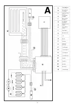
Electrical Connection

WARNING – THIS APPLIANCE MUST BE EARTHED

The installation of this appliance should  be carried out by a competent electrician in accordance with I.E.E. Regulations for Electrical 
Equipment.  The radiator is 

fi

 tted with two 

fl

 exible cables for connection to the 

fi

 xed wiring of the premises through suitable connection 

boxes positioned adjacent to the radiator.  Each supply circuit to the radiator must incorporate a double pole isolating switch having a 
contact separation of at least 3mm.  This radiator is 

not

 suitable for connection to a 30A ring circuit.

THESE INSTRUCTIONS SHOULD BE READ CAREFULLY AND RETAINED FOR FUTURE REFERENCE

NOTE ALSO THE INFORMATION GIVEN ON THE APPLIANCE

IMPORTANT SAFETY ADVICE

WARNING - 

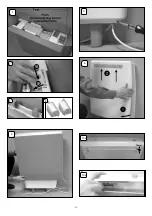
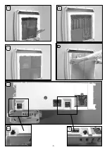
This radiator is VERY HEAVY, it is essential that the radiator is FIXED SOUNDLY TO A WALL and mounted on a 

FIRM, LEVEL SURFACE.  

WARNING 

– Choose the appropriate 

fi

 xings to securely attach the radiator to the wall; 


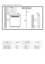
Suggested Wall Fittings 

(see page 5 for further information)
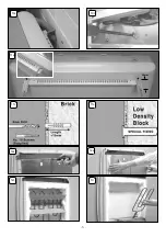
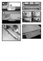
  

Solid 

brick/block:

 Size 10 plastic inserts (provided). 8mm drill bit. Drill 15mm deeper than insert  length.

 Plasterboard:

  If possible locate studding and use No. 10 woodscrews directly into the wood, otherwise M5 

intersets. 

 For other wall types seek specialist advice.

WARNING

 – If during any reassembly of the radiator, a part of the thermal insulation shows damage or deterioration which may 

impair safety, it should be replaced with an identical part.

WARNING 

– This radiator must not be located below a 

fi

 xed socket outlet.

WARNING

 - in order to avoid overheating, do not cover the radiator.

DO NOT COVER OR OBSTRUCT

 the surfaces of the appliance.

DO NOT POSITION

 under windows where curtains may contact the radiator (see minimum clearances on Page 3).

DO NOT PLACE OBJECTS

 in contact with the radiator.

This appliance is not intended for use by persons (including children, who should be supervised) with reduced physical, sensory 

or mental capabilities,  unless supervision or instruction has been given concerning use of the appliance by a person responsible 
for their safety.

DuoHeat Radiators are not suitable for installation in bathrooms, shower rooms etc. or in areas of high humidity.

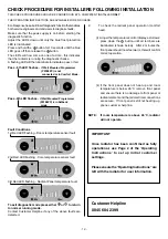
TO ENSURE THIS APPLIANCE IS OPERATING CORRECTLY, IT IS ESSENTIAL TO PERFORM THE CHECK PROCEDURE DETAILED 

ON THE BACK PAGE OF THIS INSTRUCTION. THIS 

MUST

 BE COMPLETED BEFORE NORMAL OPERATION COMMENCES.

ATTENTION : IN ORDER TO AVOID OVER HEATING DO NOT COVER THE HEATER

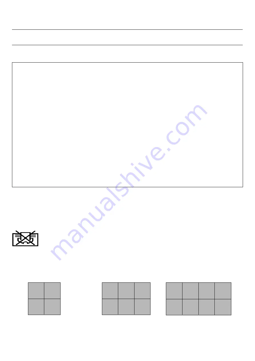
Energy Retention Cells

Energy retention cells are supplied separately to the radiator in packs of two.
The reference number is 

75-779999

.

ER300
8 Cells (4 Packs)

ER400
12 Cells (6 Packs)

ER500
16 Cells (8 Packs)

Summary of Contents for 75773301

Page 1: ... 1 ER300 75773301 1 3kW 0 38kW 9 1kWh ER400 75773302 1 95kW 0 47kW 13 65kWh ER500 75773303 2 6kW 0 54kW 18 2kWh 87956 Issue 3 April 2010 Installation Instructions Storage Radiant Heaters ...

Page 2: ...G Core Sensing Thermistor H Charge Controller Module I User Interface Module J Peak Supply K Radiant Element L Live N Neutral P Pilot Wire E Manual Fit Connector L1 Live Storage In L2 Live Storage Out L3 Live Radiant In L4 Live Radiant Out S1 Signal In S2 Signal Out N1 Neutral In N2 Neutral Out M Off Peak Supply ER300 ER400 ER500 ...

Page 3: ...struction 110mm 150mm min 250mm min 75mm min 75mm min A B C Model Height Width Depth ER300 75773301 712mm 600mm 130mm 10mm ER400 75773302 712mm 830mm 130mm 10mm ER500 75773303 712mm 1060mm 130mm 10mm Dimensions including clearances diagram millimetres A B C ...

Page 4: ... 4 2 1 6 4 1 2 10mm 10A 10B 2 1 2 2 2 5 ...

Page 5: ... 5 30mm 10E 10F 11A 11c 11D 12A 12B 12C 13 ...

Page 6: ... 6 16 14 15A 15B 18B 18 18A ...

Page 7: ... 7 2 1 19A 19B 19C 19E 19F 19D 19G 19H ...

Page 8: ... For other wall types seek specialist advice WARNING If during any reassembly of the radiator a part of the thermal insulation shows damage or deterioration which may impair safety it should be replaced with an identical part WARNING This radiator must not be located below a fixed socket outlet WARNING in order to avoid overheating do not cover the radiator DO NOT COVER OR OBSTRUCT the surfaces of...

Page 9: ...r ensuring it is secure during transit The off peak mains cable will be secured with clips Prior to installing the radiator unclip the direct acting mains cable do not remove or discard these clips NOTE If the off peak mains connection is required to be made on the right hand side of the radiator the pre wired cable must be passed behind the feet and secured using the clips on the base of the radi...

Page 10: ...g the screws along its top edge Fig 12A Carefully lift the bottom of the front inner panel out of the retaining flange at the base of the radiator Fig 12B and remove the internal packaging Fig 12C taking care not to damage the insulation attached 13 Lift out the elements from the base insulation and rotate forwards Fig 13 DO NOT DISCONNECT THE TERMINALS 14 Carefully fit the bottom row of the back ...

Page 11: ...CABLE BE PUSHED INSIDE OR BEHIND THE RADIATOR CHECK ALL ELECTRICAL CONNECTIONS FOR TIGHTNESS IMPORTANT 20 The wires in the direct acting supply cable are coloured in accordance with the following code GREEN YELLOW EARTH BLUE NEUTRAL BROWN LIVE BLACK PILOT WIRE ELECTRICAL CONNECTION The BLACK pilot wire is designed to carry a signal from a compatible remote programming device If however a remote pr...

Page 12: ...diagnose faults Make sure that the peak supply is on before starting the diagnostic function Adjust the LED s down until only the blue frost protection LED is illuminated Press and hold the button for 10 seconds until the blue LED goes off then release the button The LED s will now come on one at a time this indicates that the radiator is running the diagnostic checks A flashing LED will then illu...

Reviews: