

- 9 -
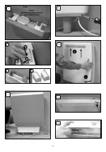
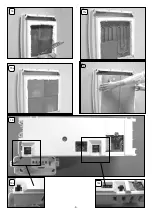
5. Stand the radiator on its feet and against a wall. Remove
the securing screws along the bottom edge of the front
panel. (Fig. 5)
6. Carefully swing bottom of panel slightly away from the
rest of the radiator
1
, thus disconnecting the radiant element
connector from the front panel, and lift upwards to unhook
the top edge
2
. (Fig. 6).
4. Stand the radiator on its feet and remove packaging.
Remove all additional internal protective packaging. (Fig. 4)
7. Ensure the electronic components are not damaged when
removing the panel. Carefully place the panel to one side.
Check that the mains supply cables are not damaged.
If they are to be replaced only heat resistant cable must be
used (min. T85) for both the off peak cable and peak. Refer
to sections 3, 19 and 20 for
fi
tting the off peak and radiant
element cables.
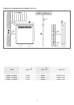
8. Position radiator against wall in intended
fi
nal position,
ensuring it is on a
fi
rm base and taking note of the minimum
fi
xing dimensions (see page 3).
9. If the
fl
oor is carpeted it is important that the feet are po-
sitioned
fi
rmly and securely. The feet may rest on top of the
carpet, however carpet gripper should be removed around
the feet so that the radiator rests in a level position.
1. Open carton from the bottom. Remove feet, plinth and
accessories bag from the polystyrene packaging. (Fig. 1)
2. Before removing the radiator from the carton, fit
the feet to the radiator by engaging the
fl
anges on the
top of the foot with the slots in the base of the radiator
1
. Push the foot towards the back of the radiator until it is
fully engaged
2
. (Fig. 2)
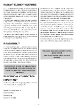
ASSEMBLY
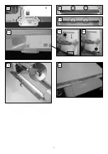
3. The direct acting mains cable is clipped to the underside
of the radiator ensuring it is secure during transit. The
off peak mains cable will be secured with clips. Prior to
installing the radiator, unclip the direct acting mains cable
(do not remove or discard these clips).
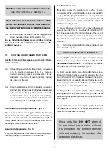
NOTE: If the off peak mains connection is required
to be made on the right hand side of the radiator, the
pre-wired cable must be passed behind the feet and
secured using the clips on the base of the radiator. For
ease of access this should be done while the radiator
is still upside down in the carton. Similarly when the
direct acting mains cable is ready to be connected (See
Section 19), if the connection is required to be made
on the left hand side of the radiator the cable must be
routed behind the feet. DO NOT clip the direct acting
mains cable at this stage (See Section 19). The cable
clips are already
fi
tted at the factory to allow both mains
cables to be attached, if required.
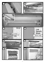
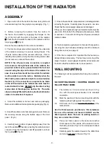
The following must be applied before
fi
xing the radiator to
the wall:
NO SKIRTING BOARD / SKIRTING BOARD NO
TALLER THAN 100MM
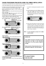
10
A
The radiator is to be mounted as shown in Fig.
10
A
, with the wall spacer bracket in its standard
orientation.
10
B
Mark the position of the two mounting slots with the
radiator pushed tight against the wall Fig. 10
B
.
WALL MOUNTING
10
C
Drill holes into the wall
toward the bottom
of the
marked slots.
Use the 10mm spacers provided (4 x 10mm) between
the rear of the radiator and the wall. DO NOT use the
30mm spacers where there are no skirting boards or
they are no taller than 100mm.
10
D
Place one 10mm spacer to the inside and another
10mm spacer to the outside of the location hole on
the back panel (see Fig 10
A
for wall spacer bracket
orientation).
10
E
Carefully guide the radiator towards the drilled hole
and screw
part way
to the wall Fig. 10
E
.
INSTALLATION OF THE RADIATOR
Ensure feet are attached in the correct orientation.


