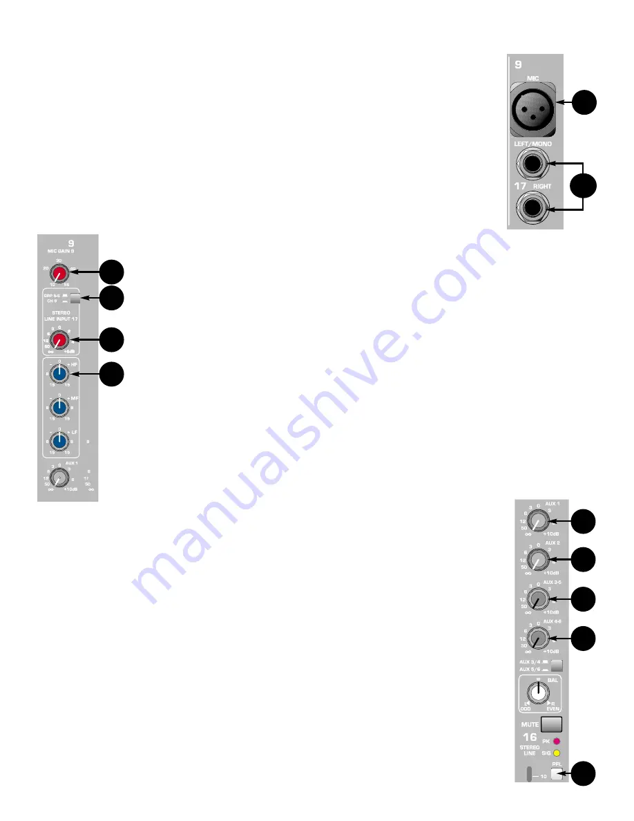
CHANNEL 9 — 16 AND 17 — 24 (BACK PANEL CONNECTIONS)
37. MICROPHONE
INPUT
The MICROPHONE INPUT is an XLR balanced input for a low impedance
microphone. Pin 2 is the positive input.
38.
STEREO LINE INPUT
These two 1/4" (TS) unbalanced line inputs LEFT/MONO and RIGHT are for
high level, line signals. If there is no 1/4" jack plugged into the RIGHT input,
the signal from the LEFT/MONO jack is applied to both L and R inputs. On
the stereo Channels 15 and 16, if selected, the LINE INPUT signals are sent
directly to the L and R sub-channels.
CHANNEL 9 — 16 AND 17 — 24 (FRONT PANEL FEATURES)
39. GAIN
The GAIN CONTROL varies the gain of the microphone input to allow a
wider input dynamic range. The gain adjustment range is +10 dB to
+50 dB. Proper adjustment of the mic gain will maximize the signal to
noise ratio. It can be set by depressing the PFL switch (35) and adjusting
for a 0 dB level at the R meter.
40.
CHANNEL 17 — 24 ASSIGNMENT SWITCH
This switch determines how the stereo line inputs are routed. In the out
position, the signal is routed to sub-group 5/6. When the switch is
depressed, the mic input on the corresponding input channel (9 - 16) is
muted and the line signal is routed through that channel. On channels 9 -
14, the signal is summed mono. On channels 15 and 16, the stereo
signal is maintained.
41.
LINE INPUT LEVEL
The line input level control adjusts the stereo line input from (-) infinity to
unity gain at the center detent, and to +6 dB at the full clockwise position.
When assigned to group 5/6, this control is the input mix
control. When routed through the corresponding channel
strip, this control serves as the input trim control.
42.
MID (dB) EQ
This bandpass (boost/cut) active tone control varies the
mid-frequency /-15 dB with a fixed center
FREQUENCY of 800 Hz.
(All remaining controls and features are identical with those on Channels 1-8.)
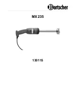
CHANNEL 15 AND 16 (STEREO CHANNELS)
These two channels are full stereo channels with two separate L and R sub-channels
each. All controls and functions are identical with those on Channels 9 — 14 with the
following exceptions:
43. AUX
1/2
AUX 1 adjusts the level of the channel’s LEFT pre-fader signal that
is added to AUX 1 mix. AUX 2 adjusts the level of the channel’s RIGHT pre-
fader signal that is added to AUX 2 mix. Unity gain at the center detent
position and +10 dB of gain in maximum.
16
39
40
41
42
43
43
44
44
45
37
38
Summary of Contents for CPM 2462
Page 20: ...20 CPM 2462 Block Diagram VIII ...
Page 21: ...21 RSM 4062 Block Diagram ...
Page 22: ...22 ...
Page 23: ...23 ...
Page 24: ...24 ...
Page 29: ...29 CPM 2642 Ch 3 8 Mid EQ ...
Page 30: ...30 CPM 2642 Channel Shelving EQ and LC Filter ...
Page 31: ...31 CPM 2642 Channel 15 Mid ...
Page 32: ...78 NOTES ...
Page 33: ...NOTES ...
Page 34: ...NOTES ...


