52.
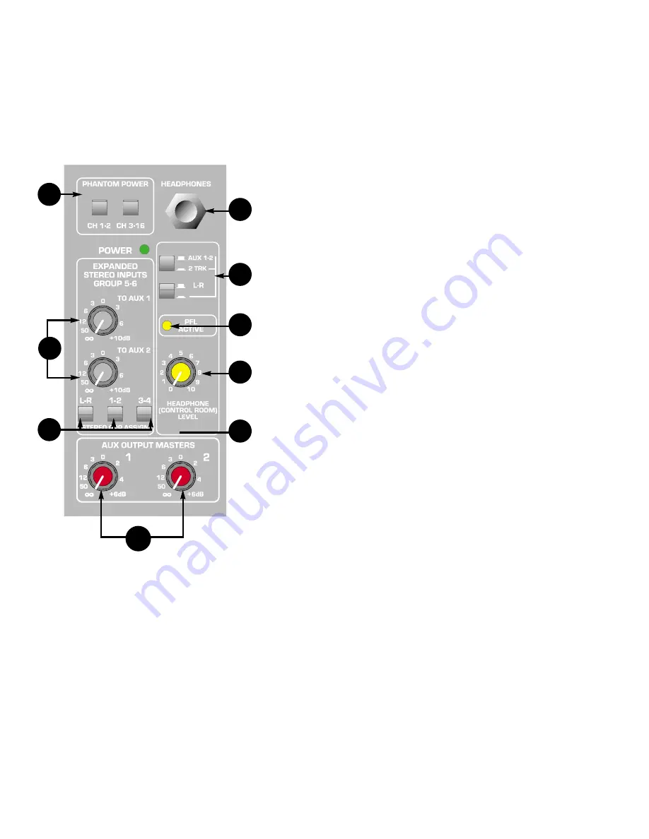
AUX 1-2 MASTERS
These controls set the levels of the AUX 1-2 channels sent to the output connectors. It ranges
from (–)infinity, to unity gain at the center detent position (reference setting), to +6 dB at full
clockwise.
53. GROUP 5/6
ASSIGNMENT
SWITCHES
These switches connect the Group 5/6 signal to MASTER L/R, GROUP 1/2 and GROUP 3/4
buses.
54.
GROUP 5/6 TO AUX 1 and AUX 2 CONTROLS
These two rotary controls set the level of the GROUP
5/6 signal sent to AUX 1 and AUX 2. Adjustments
range from (–)infinity, to unity gain at the center
detent position (reference setting), to +10 dB at the
full clockwise position.
55. HEADPHONE
OUTPUT
This stereo (TRS) jack, located on the front panel,
provides the signal to drive stereo headphones.
Tip=Left, Ring=Right, Shield=Ground. The level at
the Headphones and Control room outputs is set by
the headphone level control (56). These two outputs
listen to L/R Master output (default) or choice of
2TRK input or AUX 1 - 2 signals according to the
position of the corresponding L/R–AUX 1 - 2 –2TRK
switches in the headphone master section. When
one of the PFL switches on any channel or
Group is engaged, these outputs listen to the PFL
(mono signal in both headphones).
56. HEADPHONE/CR
LEVEL CONTROL
This control adjusts the level of the stereo
Headphone and Control room outputs.
57.
L/R-AUX 1 - 2 -2TRK SELECTORS
These two switches select which source signal (L/R,
AUX 1 - 2 or 2TRK input) is to be monitored on the headphone and CR outputs, when none of the
PFL switches on neither Channel nor Group is engaged.
58. PFL ACTIVE
This yellow, master PFL LED blinks when the PFL is active and its signal is overriding
the default L/R mix in the headphone and CR outputs and at the L-R meters. The signals that
are present in the PFL mix can be identified by the individual LEDs lit near the corresponding
Channel or Group PFL switch.
59.
PHANTOM POWER CHANNEL 1—2, CHANNEL 3—16
These two switches apply the +48V DC phantom power to the mic inputs of Channels 1-2 or
Channels 3-16 separately. Engaging Channels 1-2 switch on the master section a48V
DC to the microphone XLR connectors of Channels 1 and 2 to power condenser microphones
that require it. Respectively, engaging Channels 3-16 switch a48V DC voltage to the
microphone XLR connectors of Channels 3 through 16.
52
53
53
54
60
58
56
57
55
18
Summary of Contents for CPM 2462
Page 20: ...20 CPM 2462 Block Diagram VIII ...
Page 21: ...21 RSM 4062 Block Diagram ...
Page 22: ...22 ...
Page 23: ...23 ...
Page 24: ...24 ...
Page 29: ...29 CPM 2642 Ch 3 8 Mid EQ ...
Page 30: ...30 CPM 2642 Channel Shelving EQ and LC Filter ...
Page 31: ...31 CPM 2642 Channel 15 Mid ...
Page 32: ...78 NOTES ...
Page 33: ...NOTES ...
Page 34: ...NOTES ...


