8
GROUPS 1-4 OUTPUTS
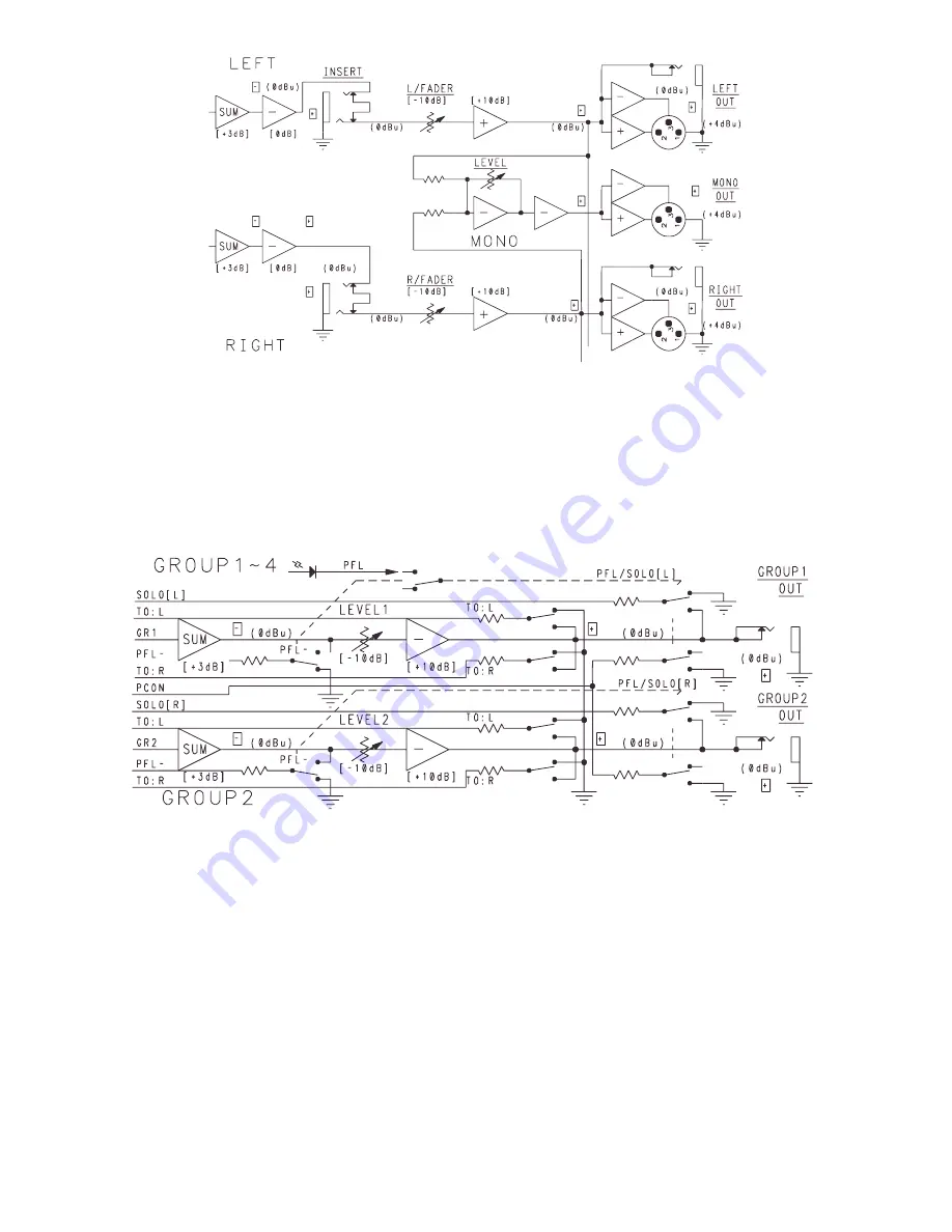
The next mix is the Group mix. Groups 1-4 are slightly different than Groups 5 and 6. Groups 1-4
have their own assign switches and faders similar to the input channels. Each group (1-4) features
a PFL switch, Left (L) switch, Right (R) switch, and a master fader. The switches assign the group
signal to the particular bus. For instance, if you group the various drums of a drum kit into Group 1,
pressing the Group 1 (L) switch would send that group mix to the Left bus. How much of that signal
present on the Left bus is determined by the group’s master fader. The following block diagram
shows Groups 1 and 2 (typical of 3 and 4).
GROUPS 5 AND 6 OUTPUTS (CHANNELS 9-16)
Groups 5 and 6 do not have faders like Groups 1-4. Groups 5 and 6 are meant to provide a stereo
signal (5-Left and 6-Right) to be placed on any of the following buses: Groups 1/2, Groups 3/4, Main
Left/Right and the Aux 1-2. All buses are selectable by switch except for the Aux 1/2 bus. The output
of Groups 5 and 6 to the Aux 1-2 is controlled by two separate rotary level controls. Groups 5 and 6
are not PFL selectable unless they are assigned to Groups 1/2, Groups 3/4, Main Left/Right or the
level is adjusted to pass the signal to the Aux 1-2. PFL can be selected from within those areas. The
following block diagram shows the Groups 5 and 6.
Summary of Contents for CPM 2462
Page 20: ...20 CPM 2462 Block Diagram VIII ...
Page 21: ...21 RSM 4062 Block Diagram ...
Page 22: ...22 ...
Page 23: ...23 ...
Page 24: ...24 ...
Page 29: ...29 CPM 2642 Ch 3 8 Mid EQ ...
Page 30: ...30 CPM 2642 Channel Shelving EQ and LC Filter ...
Page 31: ...31 CPM 2642 Channel 15 Mid ...
Page 32: ...78 NOTES ...
Page 33: ...NOTES ...
Page 34: ...NOTES ...