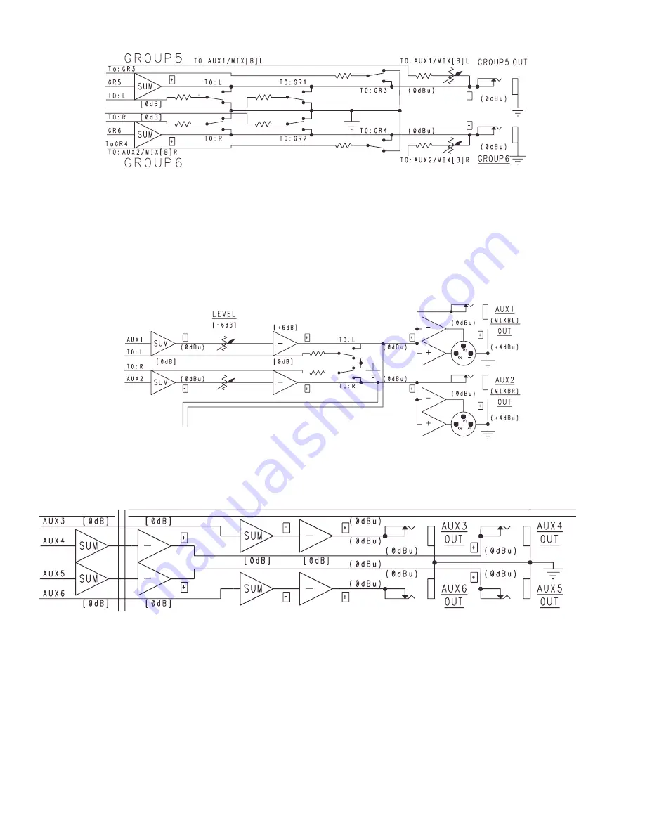
AUX 1 AND 2 OUTPUTS
Aux 1 and 2 is a pre-fader stereo mix ideal for monitor applications. As mentioned in the
previous section, Groups 5 and 6 can be sent to this Aux mix by adjusting the separate level
controls see number 54, page 18. The Aux/MIX B Master section provides an Aux 1 level
control, an Aux 2 level control.
9
AUX 1 (B) L
AUX 3, 4, 5 AND 6 OUTPUTS
Aux 3, 4, 5 and 6 are quite simple in structure. Each signal is routed to its respective output.
Levels on these Aux mixes are controlled by the individual input channel controls for the
respective Aux channel. The following block diagram shows the Aux 3, 4, 5 and 6 signal flow.
HEADPHONE AND CONTROL ROOM OUTPUTS
The last section is the Headphone/Control Room section. The purpose of this area is to provide
the headphone output and control room output as well as determine what mix is present at
those outputs. This section also provides the Tape In/Out functions of the CPM 2462. Up to this
point we haven’t discussed the PFL function very much. Since these are monitored in the
headphones and/or control room mixes they are included here as well. Both levels are
determined by the Headphone/Control Room Level control.
The following block diagram shows the Aux 1 and 2 signal flow.
Summary of Contents for CPM 2462
Page 20: ...20 CPM 2462 Block Diagram VIII ...
Page 21: ...21 RSM 4062 Block Diagram ...
Page 22: ...22 ...
Page 23: ...23 ...
Page 24: ...24 ...
Page 29: ...29 CPM 2642 Ch 3 8 Mid EQ ...
Page 30: ...30 CPM 2642 Channel Shelving EQ and LC Filter ...
Page 31: ...31 CPM 2642 Channel 15 Mid ...
Page 32: ...78 NOTES ...
Page 33: ...NOTES ...
Page 34: ...NOTES ...


