background image

PRELIMINARY

INTRODUCTION

Congratulations on your purchase of the CREST 2.4 On Board Train Engineer Wireless 
Control System

2.4 TRAIN ENGINEER

 INSTRUCTION MANUAL 

NS

     Page 

1

 of 

39

Summary of Contents for Train Engineer Revolution CRE 57000
Page 1: ...PRELIMINARY INTRODUCTION Congratulations on your purchase of the CREST 2 4 On Board Train Engineer Wireless Control System 2 4 TRAIN ENGINEER INSTRUCTION MANUAL NS Page 1 of 39...

Page 2: ...Contents 2 4 TRAIN ENGINEER INSTRUCTION MANUAL NS Page 2 of 39...

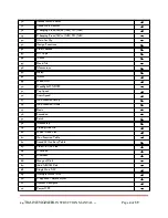
Page 3: ...Power On Of 12 15 T T Cab Control 12 16 Stop Enter 12 17 Arrow Functions 12 18 Menu 12 19 All Stop 12 20 Number Letter 12 21 Number Key 1 6 12 22 Number Key 12 23 Number Key 0 all stop 12 24 View MU...

Page 4: ...5 51 Top Speed 25 52 Start Speed 25 53 Aux Function Setup 26 54 Aux Function Mode 26 55 Basic 26 56 Extended 26 57 Latch 26 58 Momentary 26 59 Linking Link Ok 27 60 Quick Menu List 28 61 Aux Function...

Page 5: ...88 Powering the On Board Receiver 38 89 Connecting the Power Wires 38 90 Isolate the Motor Wires 38 91 Connecting the Headlights 38 92 Securing the On Board Receiver 38 93 Plug in the Receiver to the...

Page 6: ...Peak Loads That Can Go to 8 amps Range of 300 Indoors Single Unit SU Six Auxiliary Outputs on the Receiver Multi Units MUed 6 locomotive Smoke Control Sixteen Function Accessories 1 SYSTEM COMPONENTS...

Page 7: ...2 4 Transmitter Receiver Code Set Switch Auxiliary Wire Harness Smoke Control Wire Harness 2 1 TRANSMITTER DIAGRAM AND COMPONENTS 2 4 TRAIN ENGINEER INSTRUCTION MANUAL NS Page 7 of 39...

Page 8: ...y Menu Button Reverse Direction Left Arrow Fast Speed Up Arrow Choose Cab Number Step Speed PWC Linear Power DL Delay Cab Active Locomotive Antenna Signal SU MU Locomotive Name Top Speed Locomotive Di...

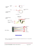
Page 9: ...CTION MANUAL NS Page 9 of 39 Plug to Seven Pin Aux Socket 3 Code Set Switch Code Set Button Common To Aux Functions 4 Auxiliary Wire Harness Plug to smoke units Art 29311 5 Smoke Control Board Connect...

Page 10: ...lect the Cab number that it will run under This allows you to easily move between as many as 50 locomotives while operating The Cab number is also used to identify groups of locomotives that you might...

Page 11: ...the smoke switch on the locomotive is in the ON position h The smoke unit must be in the LATCH position on the aux function 7 WIRE HARNESS a Use the wire harness to hook up locomotive with out the ne...

Page 12: ...smitter is turn ON or OFF d Plug the charger jack in the transmitter to charge the batteries e When charging the battery the battery icon will move indicating it s charging f When the batteries are fu...

Page 13: ...to select a locomotive and press the up arrow K View MU Locomotive When locomotives MU press the left bottom key on the transmitter to view the locomotives that MU To activate a locomotive functions e...

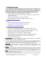
Page 14: ...tly on the engine PC board c Select track or Battery power on the switch panel on the locomotive d Apply power to the track e Press the ON OFF on Transmitter and the LCD screen will show up Press the...

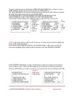
Page 15: ...croll down to M LINKING and press the Stop Enter button After a few seconds the locomotive headlight will stop flash and the transmitter will read LINKING PASSED If the LINKING failed check to make su...

Page 16: ...g the right or left arrow Scroll down to SU 49 L49 SU comes with a default LINK Address which is number 49 To enter LINK address 00 quickly press the STOP ENTER button Press the left or right arrow to...

Page 17: ...ter and Receiver a Press the Left or Right Arrow for forward and reverse Direction b To know which direction the locomotive is going look on the LCD screen and the DIR arrow will show the direction of...

Page 18: ...ct ASSIGN FUNCTIONS To enter multiple locomotives MU under ASSIGN FUNCTIONS first you have to enter a LINK address for each locomotive Each locomotive must have its own LINK address The LINK ADDRESS c...

Page 19: ...ansmitter comes with a default setting of 5 cab To control more cab press the right arrow Default Setting Add More CABS Press the MENU button one time to go back one step and scroll down to ADD MU SU...

Page 20: ...en you will see the locomotives that you MU Only one locomotive will show up on the main screen that you MUed 17 VIEW INDIVIDUAL MU LOCOMOTIVE To view MU locomotives press the bottom left key on the t...

Page 21: ...u have the smoke unit hooked up to auxiliary function F3 scroll down to F3 and press the left arrow for LATCH Do not use the momentary for smoke because it will turn the smoke on and off very quickly...

Page 22: ...shed go to SU 00 L49 and select the locomotive the above locomotives Each loco must have its own cab number and link address Do not confuse yourself with LINK ADDRESSES AND CAB NUMBERS MULTI UNITS MU...

Page 23: ...y a Press the left T key until CAB 0 show up on the main operating screen The top line on the main operating screen will show SU SD45 b Press the right T key for CAB 1 and the GP40 will show up c Pres...

Page 24: ...To enter this function press the MENU button once All functions listed below will enter in upper and lower case by using the left or right arrow a LINK ADDRESS 00 49 The link address comes with a def...

Page 25: ...et to normal NOR h HD DIR Rev Nor sets the direction that the locomotive will be traveling for the headlight to be lit This can be set to NOR normal or REV reverse If set to normal NOR the headlight o...

Page 26: ...ll make any aux function work continuously If you have the bell sound hook up to F1 on the AUX output and 1 key is pressed on the transmitter this will turn the Latch Function ON To turn OFF Latch Fun...

Page 27: ...en the red LED on the receiver board and the locomotive s lights begin flashing 3 While the lights are flashing select menu item m LINKING and press the STOP ENTER button 4 In a moment the screen will...

Page 28: ...e 28 of 39 AUX OUT ON RX PRESS KEY ON TX TO ACTIVATE SOUND ETC FUNCTIONS BASIC FUNCTION EXTENDED FUNCTION F1 1 LATCH MOMENTARY F1 F1 F2 2 LATCH MOMENTARY F2 F2 F3 3 LATCH MOMENTARY F3 F3 F4 4 LATCH MO...

Page 29: ...ry Plug can be wired in parallel with reed switches so that your sound card can ring its bell or sound its whistle from buttons on the transmitter and from magnets on the Cab that the trigger reed swi...

Page 30: ...smitter if the temperature reaches 180 degrees Fahrenheit If the receiver overheat wait for 5 to minutes for the receiver to reach it s temperature and press the 0 key on the transmitter and that will...

Page 31: ...Cab 0 Link Address 00 SD45 2nd loco on Cab 1 Link Address 01 GP40 3rd loco on Cab 2 Link Address 02 Dash 9 Choose a different Cab number to run the MUed locomotives e g Cab 3 If you enter a locomotiv...

Page 32: ...loco press the STOP ENTER button to copy To exit press the MENU button twice 2 4 TRAIN ENGINEER INSTRUCTION MANUAL NS Page 32 of 39 4 COPY LOCO FROM 00 SD45 TO 01 SD45 COPY 00 01 4 COPY LOCO FROM 00 S...

Page 33: ...ONTRAST 0 100 use this function to adjust the text color or number color on the LCD screen by pressing the left or right arrow d KEY TONE ON OFF uses this function to turn the sound tone on the transm...

Page 34: ...ter and will self generate the same number for each cab assigned 30 7 MY MEMO Name Info To exit press the MENU button twice 31 8 RESET MEMORY 1 To reset the transmitter to the factory settings press t...

Page 35: ...e the setting of each function by highlighting it and pressing STOP ENTER b AUX FN MODE OUT PUT Under the aux function mode output you can only change the Latch to ON or OFF by pressing the STOP ENTER...

Page 36: ...increments of 0 5 When step speed is set to 3 it changes in increments of 1 0 When step speed is set to 4 it changes in increments of 2 5 When step speed is set to 5 it changes in increments of 5 0 St...

Page 37: ...of at least 12volts DC to a maximum of 24 volts DC The unit is self protected for polarity and input current b CONNECT THE POWER WIRES Solder the black TR wire and red TR wire from the Wire Harness A...

Page 38: ...BLUE HEADLIGHT COMMON HD 2 WHITE FRONT HEADLIGHT e SECURING THE ON BOARD The On Board should be insulated and secure from any metal inside the engine The On Board can be attached to the shell or inte...

Page 39: ...2 4 TRAIN ENGINEER INSTRUCTION MANUAL NS Page 39 of 39...

Page 40: ...rference will not occur in a particular installation If this equipment does cause harmful interference to radio or television reception which can be determined by tuning the equipment off and on the u...

Reviews: