Crestron
C2N-CAMIDSPT
Camera Interface, Digital Servo Pan Tilt Head
Operations Guide - DOC. 6262A
Camera Interface, Digital Servo Pan Tilt Head: C2N-CAMIDSPT
•
9
RS-232
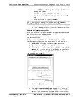
This DB9 male connector is primarily used for communication with and control of
“smart” cameras (serial-port-controlled cameras). To properly wire the mating
connector, refer to the following diagram and pinout table.
CAMIDSPT Pinout for RS-232 Port
PIN DESCRIPTION
1 No
connection
2
Receive data
3 Transmit
data
4
No connection
5 Signal
ground
6
No connection
7
Request to send
8
Clear to send
9 No
connection
CAMIDSPT Indicators
Three indicators are located on the side panel of the CAMIDSPT. Refer to the
illustration shown in “CAMIDSPT Ports” on page 7 and the descriptions after this
paragraph.
PWR
This green LED illuminates when +24 VDC is supplied to the CAMIDSPT.
NET
This yellow LED illuminates when communication between the control system and
the CAMIDSPT is established. Illumination indicates that the SIMPL program
currently loaded has a network device defined at the same NET ID as the
CAMIDSPT.
SETUP
This red LED indicates firmware upgrade, data downloading, or TSID configuration
activity.
SETUP LED and Pushbutton
The SETUP pushbutton and its associated LED are to be used for setup of the unit’s
network ID during the initial configuration of a Cresnet system or when the device is
being added/replaced. Refer to “Method B (Touch Settable IDs)” on page 13
for
detailed information.
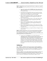
Mini Joystick
The mini joystick located on the side of the unit, protected by a dust cover, is used
for local manual operation of focus/zoom or pan/tilt motor control functions when
installing the unit. (Refer to the following illustration.)
•
The joystick center position pushbutton toggles the operating mode
between pan/tilt and zoom/focus functions.
•
Pressing the joystick to the left either pans the camera head to the right
or adjusts the lens focus.
Pin 1
Pin 9
RS-232
Connector


