Camera Interface, Digital Servo Pan Tilt Head
Crestron
C2N-CAMIDSPT
18
•
Camera Interface, Digital Servo Pan Tilt Head: C2N-CAMIDSPT
Operations Guide - DOC. 6262A
for your lens type is installed. If necessary, carefully remove the installed board and
replace with the correct type. Replace the cover plate and secure with the two screws
removed earlier.
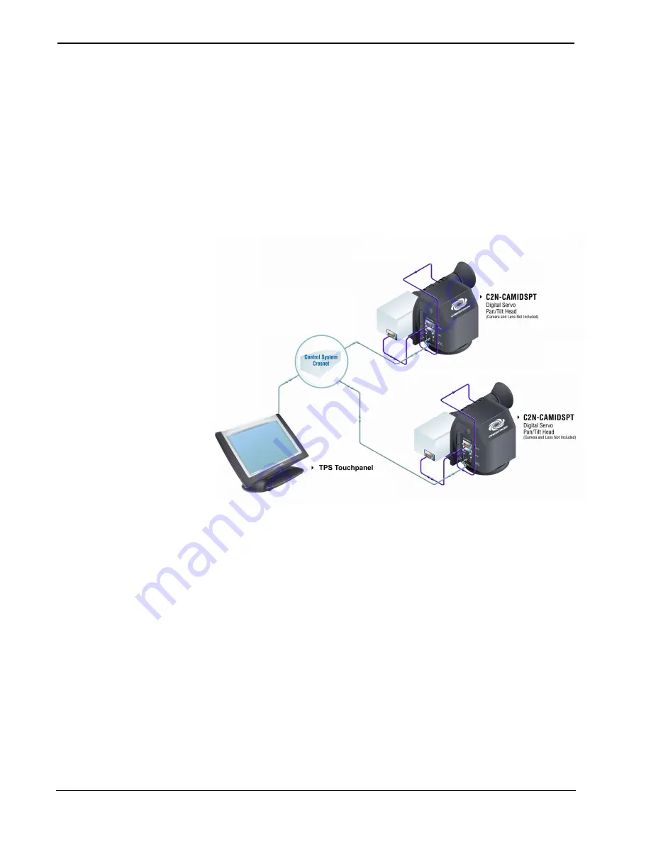
The following diagram shows a Cresnet configuration that includes a Crestron TPS
touchpanel used to operate the CAMIDSPT. Another typical configuration would
include a Crestron Camera Controller such as the CPC-2000A. (A complete
configuration for control of a remote video camera would include distribution of the
camera’s video output to a local video monitor so you can see the results of your
setting adjustments.)
Typical Configuration for Control of Remote Video Camera/Lens Functions
Power Up Conditions
At power up, the CAMIDSPT executes a short series of pan/tilt movement while it
calibrates its home position. The unit must have unrestricted movement in a range of
±30 degrees. This homing process takes approximately 15 seconds. During this time,
the unit will not respond to Cresnet commands. If no user program is running, the
pan/tilt will return to the home position. If a user program is running, the unit will
return to the last position specified by the position analog input joins.
In order for the lens output drivers to be enabled, the attached lens must be powered
up at the same time or before the CAMIDSPT is powered.
If the local joystick has been operated since the last power up, a calibration routine
will be performed.
Limit Stop Adjustment
Two adjustable stops are supplied for each rotating disk on the CAMIDSPT.
Complete the following steps to properly set the limit stops. For this procedure,
operation of the CAMIDSPT is controlled through the mini joystick. Refer to “Mini
Joystick” on page 9 for more information.


