Camera Interface, Digital Servo Pan Tilt Head
Crestron
C2N-CAMIDSPT
22
•
Camera Interface, Digital Servo Pan Tilt Head: C2N-CAMIDSPT
Operations Guide - DOC. 6262A
Setting the Net ID in Device Settings
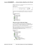
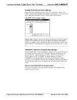
Double-click the CAMIDSPT icon to open the “Device Settings” window. This
window displays the CAMIDSPT device information. If necessary, select the
Net ID
tab to change the CAMIDSPT Net ID, as shown in the following figure.
CAMIDSPT “Device Settings” Window
NOTE:
SIMPL Windows automatically changes Net ID values of a device added to
a program if a duplicate device or a device with the same default Net ID already
exists in the program. Always ensure that the hardware and software settings of the
Net ID match. For Net ID hardware setting details, refer to “Identity Code” on page
12.
CAMIDSPT Symbol in Programming Manager
Programming Manager is where programmers “program” a Crestron control system
by assigning signals to symbols. The CAMIDSPT functions are divided into two
sub-slots: Slot 01 – General Controls, and Slot 02 – RS-232 Controls, Port A
Generic Camera for C2N-CAMIDSPT. In Program Manager, expand the
CAMIDSPT to view the individual sub-slots; then drag the desired symbols to
Detail View
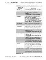
. The CAMIDSPT sub-slots and corresponding symbols are described in
the following paragraphs. Tables defining the input and output signals follow each
section.
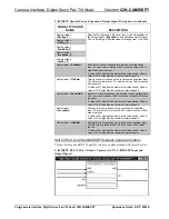
Slot 01: C2N-CAMIDSPT General Controls
This slot provides all the controls for normal operation of the CAMIDSPT and
attached cameras and lenses.


