background image

Multi-Type Network Distribution Block  

Crestron 

C2N-HBLOCK 

C2N-HBLOCK Ports 

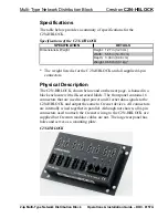
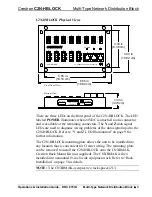
The C2N-HBLOCK contains three types of ports that are connected in 
parallel. The eight 3.5mm, 4-pin connectors (labeled 

1

,

 2

,

 3

,

 4

,

 5

,

 6

,

 7 

and


8

) and the five 5mm, 4-pin connectors (labeled 

A

,

 B

,

 C

,

 D 

and

 E

) are 

used to connect the C2N-HBLOCK to other four-wire Cresnet devices. 
The three 6-pin RJ11 modular ports (labeled 

a

,

 b 

and

 c

)


are used to 

connect the C2N-HBLOCK to modular devices in the Cresnet system. 
Only one port (any of the three types) is used as an input source and the 
remaining ports are used as outputs. 

CAUTION:  Do not connect or daisy-chain more than one power 
input (power pack or power supply) to the C2N-HBLOCK. Multiple 
power inputs may damage one or more power packs and/or power 
supplies. 

NOTE:

  When using the C2N-HBLOCK to output power to other 

devices, do not exceed the maximum capacity of the power pack or 
power supply. Calculate and add the total power requirements for all 
devices drawing power from the C2N-HBLOCK. If necessary, use 
additional C2N-HBLOCKs and power packs or power supplies. 

C2N-HBLOCK Indicators 

There are three LED indicators located on the C2N-HBLOCK front 
panel. The LEDs are described in the next three paragraphs. 

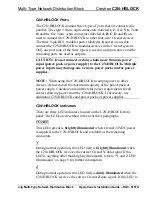
POWER 

This LED (green) is 

brightly illuminated

 when Cresnet 24VDC power 

is supplied to the C2N-HBLOCK and available at the remaining 
connectors. 

During normal operation, this LED (red) is 

brightly illuminated

 when 

the C2N-HBLOCK receives the correct Cresnet 

Y

 data signal. If this 

LED is anything other than brightly illuminated, refer to “Y and Z LED 
Illumination” on page 9 fo
r further information. 

During normal operation, this LED (red) is 

dimly illuminated

 when the 

C2N-HBLOCK receives the correct Cresnet 

Z

 data signal. If this LED is 

4  

  Multi-Type Network Distribution Block 

Operations & Installation Guide – DOC. 8157A  

Summary of Contents for C2N-HBLOCK

Page 1: ...Crestron C2N HBLOCK Multi Type Network Distribution Block Operations Installation Guide ...

Page 2: ...n by the Technical Documentation department at Crestron Electronics Inc 15 Volvo Drive Rockleigh NJ 07647 1 888 CRESTRON All brand names product names and trademarks are the property of their respective owners 2003 Crestron Electronics Inc ...

Page 3: ...try Compliance 5 Installation and Wiring 5 Installation 5 Network Wiring 6 Connecting the C2N HBLOCK to Cresnet Devices 8 Problem Solving 9 General Troubleshooting 9 Y and Z LED Illumination 9 Further Inquiries 10 Future Updates 10 Return and Warranty Policies 11 Merchandise Returns Repair Service 11 CRESTRON Limited Warranty 11 Operations Installtion Guide DOC 8157A Contents i ...

Page 4: ......

Page 5: ... of the connectors as an input source the remaining connectors may be used as outputs to other equipment The C2N HBLOCK contains light emitting diode LED indicators that monitor the input power and input data signals Functional Summary Provides wiring for up to 15 devices and or peripherals Three different types of Cresnet connectors all of which are in parallel Eight 3 5mm 4 pin screw terminal co...

Page 6: ...The C2N HBLOCK shown below and on the next page is housed in a black enclosure with silk screened labels The front panel contains 16 connectors that are used to input power and Cresnet data signals to the C2N HBLOCK and output the same to Cresnet devices All connectors are internally wired together in parallel Although not shown all 4 pin connectors used to attach the Cresnet wiring to the C2N HBL...

Page 7: ... to one connector and is available at the remaining connectors The Y and Z data signal LEDs are used to diagnose wiring problems of the data signal input to the C2N HBLOCK Refer to Y and Z LED Illumination on page 9 for further information The C2N HBLOCK mounting plate allows the unit to be installed into any location that is convenient for Cresnet wiring The mounting plate can be removed to insta...

Page 8: ... to other devices do not exceed the maximum capacity of the power pack or power supply Calculate and add the total power requirements for all devices drawing power from the C2N HBLOCK If necessary use additional C2N HBLOCKs and power packs or power supplies C2N HBLOCK Indicators There are three LED indicators located on the C2N HBLOCK front panel The LEDs are described in the next three paragraphs...

Page 9: ...te or into a rack refer to the appropriate subsection Mounting Plate Installation To install the C2N HBLOCK via the mounting plate attach the mounting plate to a convenient location and anchor the unit with a screw through at least one hole in each corner mounting screws are not supplied It is recommended to install the C2N HBLOCK in an area where the connectors are accessible and LEDs are visible...

Page 10: ...y NOTE For larger networks i e greater than 28 network devices it may be necessary to add a Cresnet Hub Repeater CNXHUB to maintain signal quality throughout the network Also for networks with lengthy cable runs or varying types of network devices it may be desirable to add a hub repeater after only 20 network devices NOTE When installing network wiring refer to the latest revision of the wiring d...

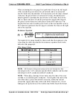
Page 11: ...ow L Length of run or chain in feet PF Power factor of entire run or chain R L x PF 40 000 Where The required wire gauge should be chosen such that the resistance value is less than the value calculated in the resistance equation Refer to the table after this paragraph Wire Gauge Values RESISTANCE R WIRE GAUGE 4 16 6 18 10 20 15 22 13 Doubled CAT5 8 7 Tripled CAT5 NOTE All Cresnet wiring must cons...

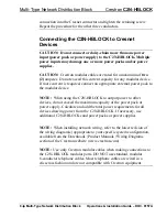
Page 12: ... HBLOCK to output power to other devices do not exceed the maximum capacity of the power pack or power supply Calculate and add the total power requirements for all devices drawing power from the C2N HBLOCK If necessary use additional C2N HBLOCKs and power packs or power supplies NOTE When installing network wiring refer to the latest revision of the wiring diagram s appropriate to your specific s...

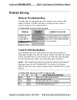
Page 13: ...ED Illumination The combination of the Y and Z data LEDs and their brightness of illumination bright dim and off indicate whether the input data signals to the C2N HBLOCK are correct Refer to the table after this paragraph for LED illuminations and the associated data signal conditions NOTE The Y and Z data LEDs are provided to denote errors with the data signal inputs to the C2N HBLOCK The LEDs d...

Page 14: ...255 5093 2160 In Australia and New Zealand call Crestron Pacific at 613 9480 2999 Future Updates As Crestron improves functions adds new features and extends the capabilities of the C2N HBLOCK additional information may be made available as manual updates These updates are solely electronic and serve as intermediary supplements prior to the release of a complete technical documentation revision Ch...

Page 15: ... are not covered This warranty extends to products purchased directly from CRESTRON or an authorized CRESTRON dealer Purchasers should inquire of the dealer regarding the nature and extent of the dealer s warranty if any CRESTRON shall not be liable to honor the terms of this warranty if the product has been used in any application other than that for which it was intended or if it has been subjec...

Page 16: ...restron Electronics Inc Operations Installation Guide DOC 8157A 15 Volvo Drive Rockleigh NJ 07647 05 03 Tel 888 CRESTRON Fax 201 767 7576 Specifications subject to www crestron com change without notice ...

Reviews: