Reference Guide
Crestron
CAT5 Wiring
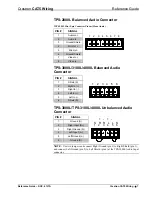
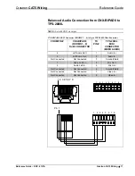
TPS-IMC-BV Balanced Audio Connector
TPS-IMC-BV RJ-45 Connector Pinout (AUDIO INPUT)
PIN #
SIGNAL
1
Mic out +
2
Mic out -
3
Mic out +
4
Audio In L +
5
Audio In L -
6
Mic out -
7
Audio In R +
8
Audio In R -
1 2 3 4 5 6 7 8
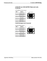
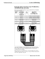
TPS-IMPC Balanced Audio Connector
This 8-pin RJ-45 mates with the TPS-3000, TPS-5000, or TPS-6000 touchpanel. The
8-pin audio cable assembly is supplied. Even though the 10-pin net/video cable may
fit into the port, do not use it. This port provides audio input to the touchpanel and
microphone output from the touchpanel.
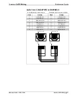
TPS-IMPC RJ-45 Connector Pinout (AUDIO)
PIN #
SIGNAL
1
Left In +
2
Left In -
3 GND/Shield
4
Right In +
5
Right In -
6
GND/Shield
7
Mic Out +
8
Mic Out -
1 2 3 4 5 6 7 8
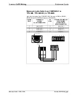
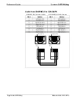
TPS-IMW Audio Connector
PIN #
SIGNAL
1 Audio
Shield
2
Audio Left +
3
Audio Left -
4
Audio Right +
5
Audio Right -
6
Mic Out
Shield
7
Mic Out +
8
Mic Out -
1 2 3 4 5 6 7 8
6
•
Crestron CAT5 Wiring
Reference Guide - DOC. 6137A


