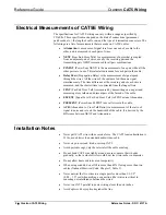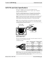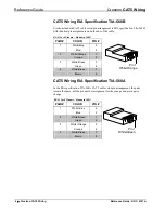
Crestron
CAT5 Wiring
Reference
Guide
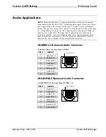
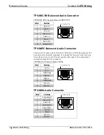
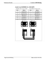
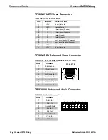
TPS-2000L Balanced Audio Connector
TPS-2000L Mini 8-pin Connector Pinout (Mono Audio)
PIN #
SIGNAL
1
Audio In +
2
Audio In -
3 Ground/Shield
4
Mic Out +
5
Mic Out -
6
Ground/Shield
7
Video In +
8
Video In -
1 2 3 4 5 6 7 8
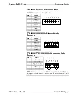
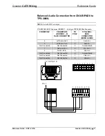
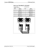
TPS-3000L/3100L/4000L Balanced Audio
Connector
PIN #
SIGNAL
1 Shield
(S)
2
Right In (+)
3
Right In (-)
4
Left In (+)
5
Left In (-)
6
Shield (S)
1 2 3 4 5 6
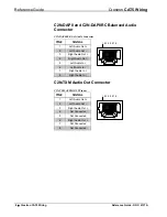
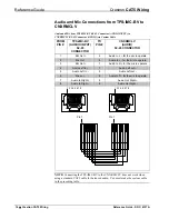
TPS-3000L/TPS-3100L/4000L Unbalanced Audio
Connector
PIN #
SIGNAL
1 Ground
(S)
2
Right Input (R+)
3
Right Ground (R-)
4
Left Input (L+)
5
Left Ground (L-)
6
Ground (S)
1 2 3 4 5 6
S R R L L S
+ - + -
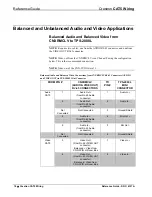
NOTE:
Use two jumpers and connect Right Ground (pin 3) to Right Shield (pin 1),
and connect Left Ground (pin 5) to Left Shield (pin 6) at the TPS-3000L Audio Input
connector.
Reference Guide – DOC. 6137A
Crestron CAT5 Wiring
•
7


