Crestron
CAT5 Wiring
Reference
Guide
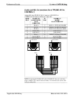
Audio and Mic Connections to Touchpanel Direct
from CNXRMCLV
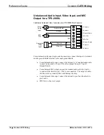
When wiring the TPS touch panel direct to the CNXRMCLV, audio on the left
channel works using either a standard CAT5 cable or the Crestron TPS Audio cable.
The MIC OUT of the TPS-IMC-BV to a CNXRMCLV does not work if you use a
standard CAT5 cable. If you wire directly to the TPS panel not using the
TPS-IMC-BV, only the right channel is available. The recommended way to wire
audio to the CNXRMCLV, and obtain both channels of audio to the TPS touchpanel,
is to use the TPS-IMC or TPS-IMW and connect the CNXRMCLV directly to the
mini connector labeled AUDIO INPUT, using a CAT5 cable. Refer to page 9 for a
diagram.
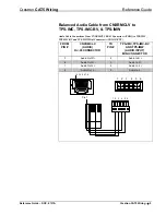
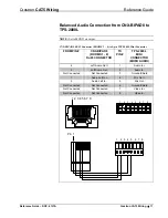
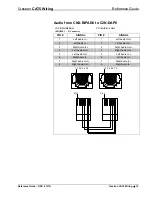
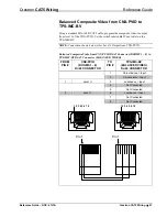
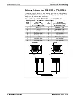
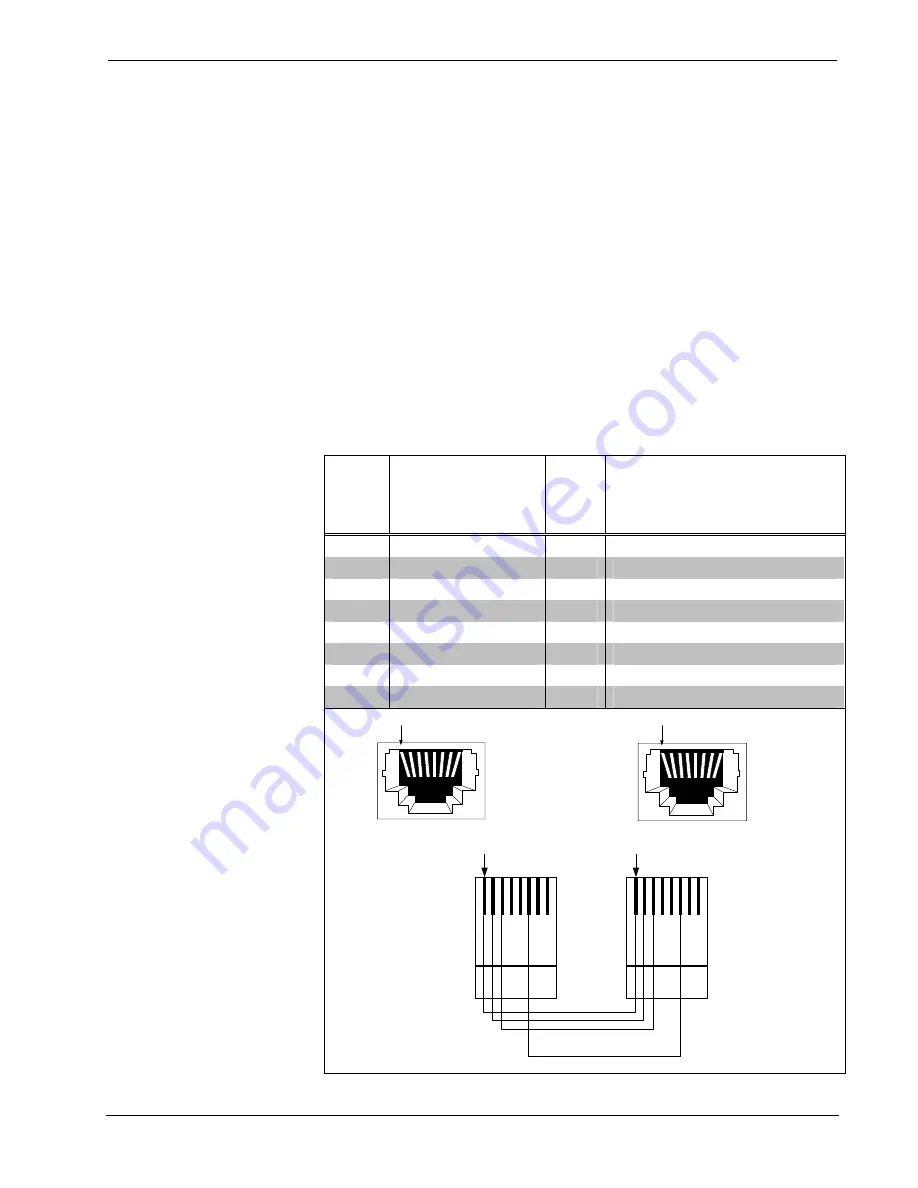
Audio Output from C2N-TXM to CNX-BIPAD8
Audio from C2N-TXM RJ-45 Connector (AUDIO OUTPUT) to CNX-BIPAD8 RJ-45
Connector
FROM
PIN #
C2N-TXM
(AUDIO OUTPUT)
RJ-45
CONNECTOR
TO
PIN #
CNX-BIPAD8
(ROOMS 1 - 8)
RJ-45 CONNECTOR
1
Audio Out L +
1
Audio In L +
2
Audio Out L -
2
Audio In L -
3
Audio Out R +
3
Audio In R
4
Not Connected
4
Not Connected
5
Not Connected
5
Not Connected
6
Audio Out R -
6
Audio In R -
7
Not Connected
7
Not Connected
8
Not Connected
8
Not Connected
1 2 3 4 5 6 7 8
1 2 3 4 5 6 7 8
Pin 1
Pin 1
Reference Guide – DOC. 6137A
Crestron CAT5 Wiring
•
17

