Crestron
CAT5 Wiring
Reference
Guide
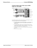
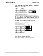
Balanced Video Applications
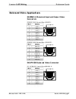
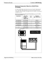
CNXRMCLV Balanced Input and Output Video
Connectors
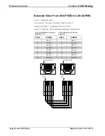
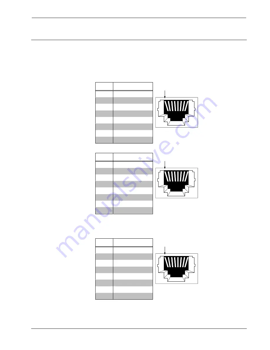
CNXRMCLV RJ-45 Connector Pinout (VIDEO IN)
PIN #
SIGNAL
1
Level 1 +
2
Level 1 -
3
Level 2 +
4
Level 3 +
5
Level 3 -
6
Level 2 -
7
Level 4 +
8
Level 4 -
1 2 3 4 5 6 7 8
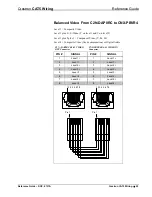
CNXRMCLV RJ-45 Connector Pinout (VIDEO OUT)
PIN #
SIGNAL
1
Output E +
2
Output E -
3
Output F +
4
Output G -
5
Output G +
6
Output F -
7
Output H +
8
Output H -
1 2 3 4 5 6 7 8
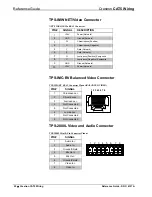
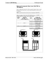
CNX-PVID8 Balanced Video Connector
CNX –PVID8 RJ-45 Connector Pinout (ROOMS 1 - 8)
PIN #
SIGNAL
1
Level 1 +
2
Level 1 -
3
Level 2 +
4
Level 3 +
5
Level 3 -
6
Level 2 -
7
Level 4 +
8
Level 4 -
1 2 3 4 5 6 7 8
Reference Guide – DOC. 6137A
Crestron CAT5 Wiring
•
21

