Crestron
CAT5 Wiring
Reference
Guide
Audio Applications
NOTE:
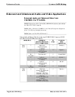
Balanced audio does not require a shield if the cable has good common
mode characteristics (such as CAT5). Unbalanced audio signals are sent on a single
wire, using ground as the reference for the signal. Ground wires are problematic
because they can carry current when exposed to electromagnetic fields or when there
is a voltage difference between the two connecting pieces of equipment. Balanced
audio uses two signal wires. The signal and its complement are sent down the
twisted pair together. Any noise picked up tends to be of equal amplitude and in
phase on both wires. At the receiver, the two signals are subtracted, and noise is
cancelled out. This technique is called common mode rejection.
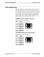
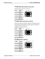
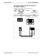
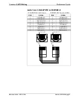
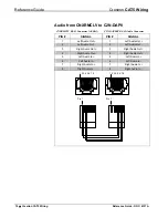
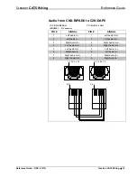
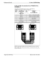
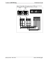
CNXRMCLV Balanced Audio Connector
CNXRMCLV RJ-45 Connector Pinout (AUDIO)
PIN #
SIGNAL
1
Audio out L +
2
Audio out L -
3
Audio out R +
4
Audio In L +
5
Audio In L -
6
Audio out R -
7
Audio In R +
8
Audio In R -
1 2 3 4 5 6 7 8
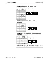
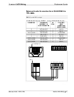
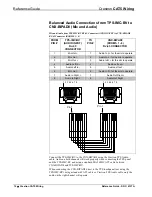
CNX-BIPAD8 Balanced Audio Connector
CNX-BIPAD8 RJ-45 Connector Pinout (ROOMS 1 – 8)
PIN #
SIGNAL
1
Audio In L +
2
Audio In L -
3
Audio In R +
4
Audio Out L +
5
Audio Out L -
6
Audio In R -
7
Audio Out R +
8
Audio Out R -
1 2 3 4 5 6 7 8
Reference Guide – DOC. 6137A
Crestron CAT5 Wiring
•
5


