Uninterruptible Power Supply
Crestron
CEN-UPS1250
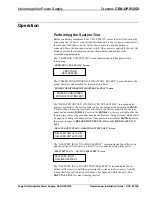
also displays the EST. RUNTIME based on the power source and connected
equipment load. In STANDBY, the unit does not provide power to the rear panel
outlets.
NOTE:
When the CEN-UPS1250 is connected to utility power, the electronics
inside the unit are active. If the front panel power switch is turned off, the unit goes
into STANDBY mode and shuts off power to the rear panel outlets but the display
remains active.
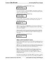
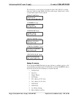
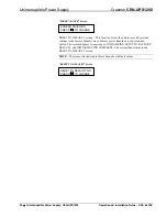
“SOURCE: UITLITY; EST. RUNTIME: XHRS” Screen
SOURCE:UTILITY
EST.RUNTIME:2HRS
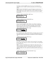
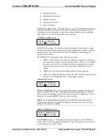
“SOURCE: BATTERY; EST. RUNTIME: XHRS” Screen
SOURCE:BATTERY
EST.RUNTIME:118MIN
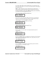
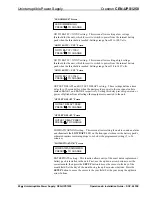
The “EST. RUNTIME: XHRS; FUEL: XXX%” screen displays the estimated
runtime as EST. RUNTIME, as well as the FUEL capacity of the internal battery
pack (as a percentage) based on the total load connected to the device. If the
estimated runtime is less than one hour, the EST. RUNTIME shows in minutes.
“EST. RUNTIME: XHRS; FUEL: XXX%” Screen
EST.RUNTIME: 2HRS
FUEL: 100%
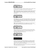
The “SYSTEM LOAD: XXXW; LOAD: XXX%” screen displays the value (load) of
the connected equipment in Watts and as a percentage of the total allowable load
connected to the unit. Loads of less than 5% of rates load (63 Watts) is displayed as
<5%.
“SYSTEM LOAD: XXXW; LOAD: XXX%” Screen
SYSTEM LOAD: <63W
LOAD: <5%
The “INPUT VOLTAGE: XXXV; OUTPUT VOLTAGE: XXXV” screen displays
the actual input utility voltage level as well as the actual voltage level being output to
the connected devices.
NOTE:
As shown in the illustration below, at times, the voltage values on the
screen may not match. This may be because separate circuits are used to make these
voltage measurements and there is a time delay between the two circuits when
updating the status screen. This condition is considered part of the normal operation
of the unit.
“INPUT VOLTAGE: XXXV; OUTPUT VOLTAGE: XXXV” Screen
INPUT VOLTAGE:124V
OUTPUT VOLTAGE:125V
24
•
Uninterruptible Power Supply: CEN-UPS1250
Operations & Installation Guide – DOC. 6635E

