2 • DM-TX-4KZ-202-C and DM-TX-4KZ-302-C
Supplemental Guide — Doc. 8325B
Physical Description
The following sections provide information about the connectors, controls, and indicators
that are available on the left and right sides of the DM-TX-4KZ-202-C and
DM-TX-4KZ-302-C.
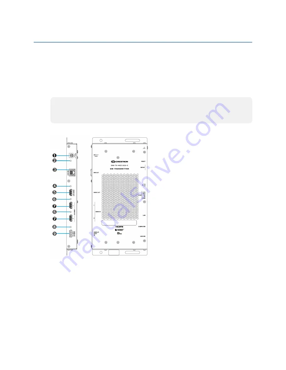
Side View, Left
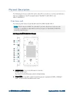
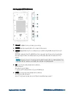
The following illustration shows the left side of the DM-TX-4KZ-302-C.
NOTE:
The left side of the DM-TX-4KZ-202-C provides the same connectors and
indicators as the DM-TX-4KZ-302-C with the exception of the DISPLAY PORT IN
connector and indicator.
Side View, Left (DM-TX-4KZ-302-C Shown)
Ê
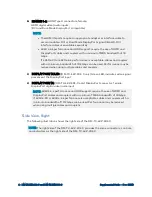
24 VDC 1.0 A: 2.1 x 5.5 mm DC power connector;
24 VDC power input;
Optional PW-2412WU power pack (sold separately)
Ë
Power LED: Green LED, indicates operating power supplied via PoDM+, HDBaseT
PoE+, or optional PW-2412WU power pack

