Wall Plate DigitalMedia™ CAT Transmitters
Crestron
DM-TX-200-2G/400-3G
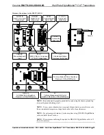
Connectors, Controls & Indicators (Continued)
# CONNECTORS,
CONTROLS &
INDICATORS
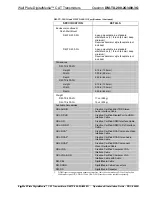
DESCRIPTION
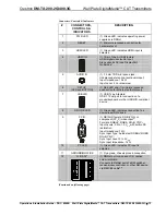
13 M
(1) DM CAT output composed of (8) captive
screw terminals with (1) grounded strain
relief;
Connects to DM CAT input of a DM switcher,
receiver/room controller or other DM device
via the yellow “M” cable of DM-CBL cable
5
;
Uses the 568-B wiring standard.
14
D
(1) DM CAT output composed of (8) captive
screw terminals with (1) grounded strain
relief;
Connects to “D” DM CAT input of a DM
switcher, receiver/room controller or other
DM device via the blue “D” cable of DM-CBL
cable
5
;
Uses the 568-B wiring standard.
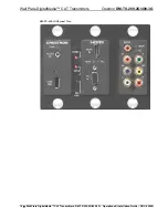
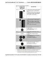
15 SPDIF
7
(1) RCA female;
S/PDIF coaxial digital audio input;
Input Impedance: 75
Ω
16
YP
b
P
r
LED
7
(1) Green LED, indicates YP
b
P
r
input is
selected
17 VID
LED
7
(1) Green LED, indicates VID input is
selected
18
Y, P
b
, P
r
7
(3) RCA female comprising (1) component
(YP
b
P
r
) video input;
Input Level: 1 V
p-p
nominal;
Input Impedance: 75
Ω
nominal
19 VID
7
(1) RCA female, composite video input;
Input Level: 1 V
P-P
nominal;
Input Impedance: 75
Ω
nominal
20
L, R
7
(2) RCA female;
Unbalanced stereo line-level audio input;
Maximum Input: 2 V
rms
;
Input Impedance: 15k
Ω
1.
HDMI requires an appropriate adapter or interface cable to accommodate a DVI or DisplayPort
Multimode signal. CBL-HD-DVI and CBL-DP-HD interface cables available separately.
2.
The RGB input can accept component, composite, and S-video signals via direct interface to
Crestron MPS Series products, or through an appropriate adapter (not included). Input sync detection
is not provided for composite or S-video signal types through the RGB connection.
14
•
Wall Plate DigitalMedia™ CAT Transmitters: DM-TX-200-2G/400-3G Operations & Installation Guide – DOC. 6949B
Summary of Contents for DigitalMedia DM-TX-200-2G
Page 4: ......


