2
•
DMF-CI-8: DM NVX and DMCF Card Chassis
Supplemental Guide – DOC. 7861C
Physical Description
This section provides information about the front and rear panels of the DMF-CI-8.
Front Panel
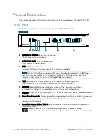
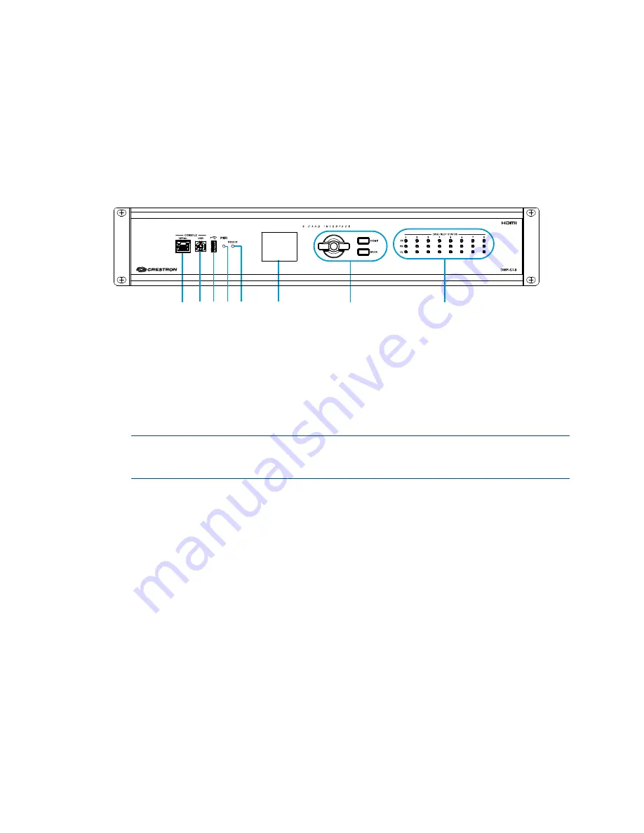
The following illustration shows the front panel of the DMF-CI-8.
Front Panel
CONSOLE, SERIAL: 8-pin RJ-45 female;
RS-232 computer console port
CONSOLE, USB: USB Type B female;
USB computer console port
USB: USB Type A female;
Supports USB mass storage devices for firmware updates
NOTE:
As an alternative to using a USB mass storage device and the USB Type A
port for firmware updates, the Crestron Toolbox™ software can be used on a
computer that connects to the USB Type B (
) console port.
PWR: Bicolor LED, amber indicates that operating power is present,
green indicates that the DMF-CI-8 has successfully initialized
STATUS: Bicolor LED, green indicates an error-free operating condition,
red indicates that an error condition exists with a card or the chassis
Display: 2-inch (52 mm) diagonal, 220 x 176 pixels, 16-bit TFT active matrix color LCD
Front Panel Controls: 5-way navigation pad and push buttons for menu navigation
and adjustment of settings (refer to “LCD Display Operation” on page 4 for
additional information)
Card Slot Status LEDs: TX 1–8, green indicates that the corresponding card is in
transmitter mode;
RX 1–8, green indicates that the corresponding card is in receiver mode;
OL 1–8, green indicates that the corresponding card is connected to a control system
Summary of Contents for DMF-CI-8
Page 4: ......

