DualTouch™ Technology Touchpanel
Crestron
DTT-17
Ports
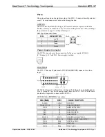
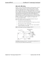
The ports are located on the right rear side of the DTT-17 under a slide-off protective
cover. The serial connector is not used in this application.
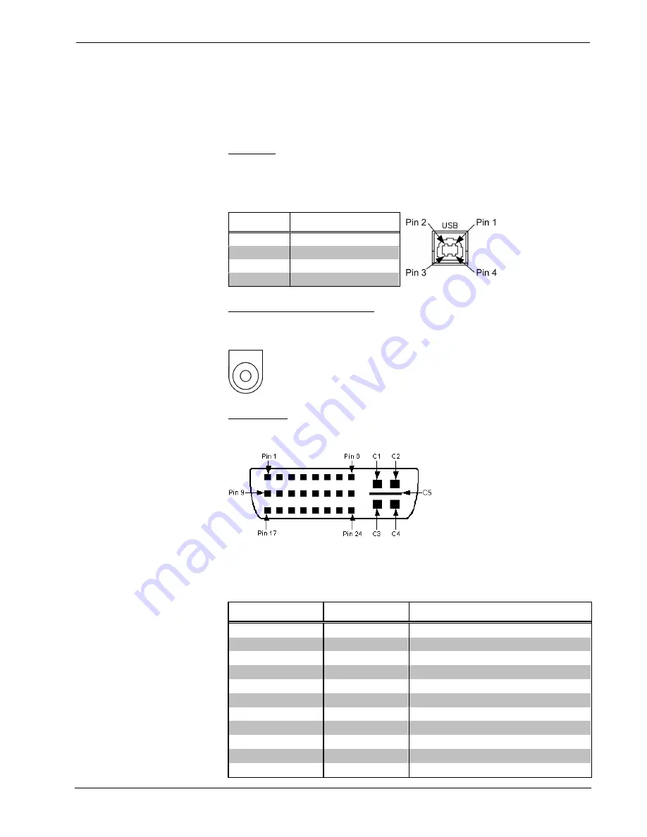
USB 2.0
One Universal Serial Bus (USB) type “B” female connector is provided for data
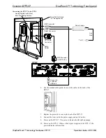
transfer, and may be connected to any of the four USB ports on the UPX-2, although
the port shown on page 10 is the preferred port.
USB Type B Connector Pinout
PIN DESCRIPTION
1 +5
VDC
2
Data -
3 Data
+
4
Ground
Power Adaptor Connector
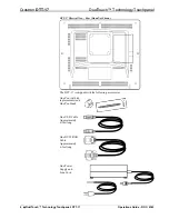
One DC IN connector provides connection for the power supply, 45 Watts
(3.75 Amps @ 12 Volts DC). Power supply included.
DVI/I RGB
The DTT-17 has one 29-pin female DVI/I RGB (DB15HD) connector for video
input.
The DVI/I (integrated) configuration is designed for both analog and digital signals.
Pins C1 through C5 are for the analog signals from the UPX-2. A DVI/I RGB cable
(included) is required to connect with the UPX-2.
DVI/I RGB Cable (
DB15HD
) Connections
VGA (RGB)
DVI/I
CABLE FUNCTION
SHIELD SHIELD
GROUND
PIN R6, G7, B8
C5
ANALOG GROUND
PIN 13
C4
HORIZONTAL SYNC
PIN 3
C3
ANALOG BLUE
PIN 2
C2
ANALOG GREEN
PIN 1
C1
ANALOG RED
PIN 5,10
PIN 15
GROUND (+5V & HV SYNC)
PIN 9
PIN 14, 16
POWER +5V/HDT PLUG DETECT
PIN 14
PIN 8
VERTICAL SYNC
PIN 12
PIN 7
DDC DATA
PIN 15
PIN 6
DDC CLOCK
Operations Guide – DOC. 6343
DualTouch™ Technology Touchpanel: DTT-17
y
7


