DualTouch™ Technology Touchpanel
Crestron
DTT-17
Setup
Hardware Hookup
Refer to the following diagrams and complete the connections as specified. Ensure
that the UPX-2 and the DTT-17 are both powered down before beginning.
CAUTION:
To avoid damage to the DTT-17 or to your video card, never connect or
disconnect the video or power cable while the DTT-17 or the UPX-2 are powered up.
NOTE:
The maximum continuous current from equipment under any external load
conditions shall not exceed a current limit that is suitable for the minimum wire
gauge used in interconnecting cables. The ratings on the connecting unit's supply
input should be considered to prevent overloading the wiring.
NOTE:
The USB cable may be extended using up to four 16-foot active extensions.
Each extension cable must contain a hub (repeater) to regenerate the USB signal
(maximum of 64 feet). For longer extensions, Crestron has tested and approved
IOGEAR USB Extender model GUCE50, which allows up to 150 feet over CAT5.
NOTE:
Using high quality cable, the VGA cable may be extended up to a
maximum of about 10 meters (32.8 ft.) for analog VGA at 1024 x 768. If you need a
longer run, add VGA extenders or VGA distribution amplifiers.
NOTE:
The native resolution of the DTT-17 is 1280 x 1024, however the resolution
actually displayed depends on the signal the UPX-2 is sending.
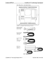
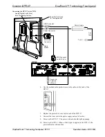
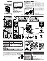
Refer to the illustrations that follow these instructions.
1. Slide off the protective cover on the rear.
2. Connect the DVI/I RGB cable, linking the UPX-2 RGB OUTPUT A
connector to the DTT-17 DVI/I RGB connector.
3. Set the Analog/Digital switch to Analog.
4. Connect the USB cable, linking the UPX-2 USB port to the DTT-17 USB
port. Use one of the preferred ports on the lower left rear side of the
UPX-2.
5. Plug the power adaptor cable into the DTT-17 DC IN port.
Operations Guide – DOC. 6343
DualTouch™ Technology Touchpanel: DTT-17
y
9


