background image

50 Watt Cresnet Power Supply 

Crestron 

GLA-PWSI50


Installation 

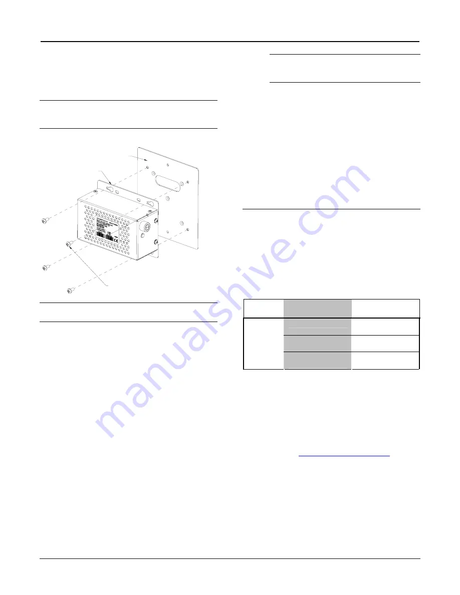
The GLA-PWSI50 mounts to the adapter plate using the 
four included screws. Refer to the following diagram 
when installing the GLA-PWSI50. 

NOTE:

  Ensure that the wires will not be pinched during 

the installation process by pushing the wires into the 
backbox.  

Install GLA-PWSI50 (Wires Removed for Clarity) 

(SUPPLIED), QUAN 4

ELECTRICAL BOX COVER SCREWS,

ADAPTER PLATE

GLA-PWSI50


NOTE:

  The GLA-PWSI50 should never be installed 

with the label facing down. 


To ensure proper ventilation, do not cover the 
ventilation holes on the front of the unit. 


Turn on the circuit breaker after completing 
installation. The green LED will illuminate 

Fuse Replacement 

If the GLA-PWSI50 does not power up when it is 
connected to line power, the fuse may need to be replaced. 
The fuse holder is located on the right side of the power 
supply (next to the LED). To replace the fuse: 

1.    Disconnect power to the GLA-PWSI50. 

2.    Use a flat-head screwdriver to push in the fuse 

holder. 

3.    While pushing in the fuse holder, turn 

screwdriver counterclockwise until the fuse 
holder pops out. 

4.    Remove the fuse from the fuse holder and insert 

a new fuse. 

CAUTION:

  Only use the specified type of fuse 

when replacing a blown fuse. Failure to do so 
may cause damage to the GLA-PWSI50. 

FUSE TYPE: 5 x 20mm 3.15A Time Lag 

5.    Insert the fuse holder into the GLA-PWSI50. 

6.    Push in the fuse holder with a flat head 

screwdriver. While pushing in the fuse holder, 
turn the screwdriver clockwise until the fuse 
holder sinks in. 

7.    Push in the fuse holder a little further and turn 

the screwdriver clockwise until the fuse holder 
locks in place. 

8.    Connect power to the GLA-PWSI50. 

Problem Solving 

Troubleshooting 

The following table provides corrective action for 
possible trouble situations. If further assistance is 
required, please contact a Crestron customer service 
representative. 

GLA-PWSI50 Troubleshooting 

TROUBLE 

POSSIBLE 

CAUSE(S) 

CORRECTIVE 

ACTION 

Circuit breaker is off. 

Verify that circuit 
breaker is on. 

Fuse is blown. 

Check fuse and 
replace if necessary. 

LED does 
not turn on. 

GLA-PWSI50 is not 
properly connected. 

Verify wiring. 

Further Inquiries 

If you cannot locate specific information or have 
questions after reviewing this guide, please take 
advantage of Crestron's award winning customer service 
team by calling Crestron at 1-888-CRESTRON  
[1-888-273-7876]. 

You can also log onto the online help section of the 
Crestron website (

www.crestron.com/onlinehelp

) to ask 

questions about Crestron products. First-time users will 
need to establish a user account to fully benefit from all 
available features. 

6  

  Wall Mount 50 Watt Cresnet Power Supply:  GLA-PWSI50 

Installation Guide – DOC. 6747A 

Summary of Contents for GLA-PWSI50

Page 1: ...PAC and other Cresnet devices Provides backup power for Crestron Green Light cabinets Compatible with 100 to 240 VAC mains Mounts to a 1 or 2 gang UK BS 4662 or Euro DIN 49073 electrical box Also compatible with 4 inch square or 2 gang US electrical boxes GLA PWS50 shown with Adapter Plate Physical View Specifications GLA PWSI50 Specifications SPECIFICATION DETAILS Output Power Output Power Ripple...

Page 2: ...al installation This equipment generates uses and can radiate radio frequency energy and if not installed and used in accordance with the instructions may cause harmful interference to radio communications However there is no guarantee that interference will not occur in a particular installation If this equipment does cause harmful interference to radio or television reception which can be determ...

Page 3: ...tt Cresnet Power Supply Application The following diagram shows a GLA PWSI50 module in a typical application GLA PWSI50 in a Lighting Application Installation Guide DOC 6747A Wall Mount 50 Watt Cresnet Power Supply GLA PWSI50 3 ...

Page 4: ...red Crestron device 3 FUSE DC output fuse T3 15AH 5x20mm 250V 3 15A time lag ceramic cartridge 4 24VDC LED 1 green LED indicates 24 Volts DC output extinguishes when fuse is blown Setup Important Notes Read before installation Permits An electrical permit shall be obtained prior to each installation Codes Install in accordance with all local and national electrical codes Wiring Use 75 C copper wir...

Page 5: ...Not Supplied Bottom 1 M3 5x25 Supplied B 2 GANG BS 4662 UK BACKBOX 2 M3 5 Not Supplied C 1 GANG DIN 49073 BACKBOX 2 M3 Not Supplied D 2 GANG DIN 49073 BACKBOX 4 M3 Not Supplied Hardware Hookup WARNING RISK OF SERIOUS PERSONAL INJURY Turn off power at the circuit breaker s prior to installation Installing with power on can result in serious personal injury and damage to the device 1 Use the include...

Page 6: ...ailure to do so may cause damage to the GLA PWSI50 FUSE TYPE 5 x 20mm 3 15A Time Lag 5 Insert the fuse holder into the GLA PWSI50 6 Push in the fuse holder with a flat head screwdriver While pushing in the fuse holder turn the screwdriver clockwise until the fuse holder sinks in 7 Push in the fuse holder a little further and turn the screwdriver clockwise until the fuse holder locks in place 8 Con...

Page 7: ...days batteries and incandescent lamps are not covered This warranty extends to products purchased directly from CRESTRON or an authorized CRESTRON dealer Purchasers should inquire of the dealer regarding the nature and extent of the dealer s warranty if any CRESTRON shall not be liable to honor the terms of this warranty if the product has been used in any application other than that for which it ...

Page 8: ...50 Watt Cresnet Power Supply Crestron GLA PWSI50 This page is intentionally left blank 8 Wall Mount 50 Watt Cresnet Power Supply GLA PWSI50 Installation Guide DOC 6747A ...

Reviews: