Crestron Isys
®
TPS-3000
6.4 Inch Tilt Touchpanel
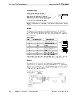
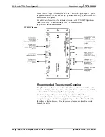
RS-232 Pinouts
PIN #
DESCRIPTION
1 CTS
2
GND
3 RXD
4
TXD
5 RTS
6
N/C (Not connected)
1
6
1
6
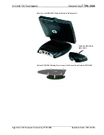
Front
Top
NOTE:
This cable is the Crestron STCP-502, and is included in the ST-PK
programming cable kit.
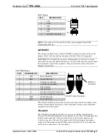
NET/VIDEO
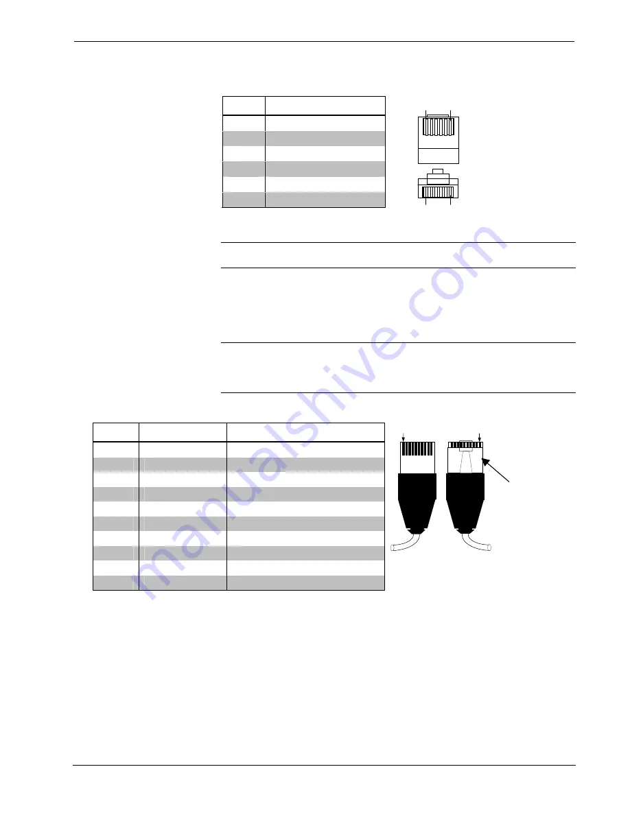
This 10-position RJ-45 mates with the TPS-IMPC interface module and has a dual
purpose. Refer to the descriptions and pinout table that follow this paragraph.
CAUTION:
The 10-pin RJ-45 connector cable supplied by Crestron is a custom
cable and is the only one that should be used. The end of the cable has a metal shield
that is required to protect the equipment. Using non-Crestron cables will result in
damage to the product.
NET/VIDEO Pinouts
PIN #
DESIGNATION
DESCRIPTION
1 +24V
Power
(Network)
2
GND
Ground (Network)
3 C+
Chrominance
(Positive)
4
C-
Chrominance (Negative)
5 Y
Data
(Network)
6
Z
Data (Network)
7
Y+
Luminance (Positive) Composite
8
Y-
Luminance (Negative) Composite
9 GND
Ground
(Network)
10
+24V
Power (Network)
Pin 1
Pin 1
RJ-45 10-pin Connector
Shield on
Connector
This 10-position RJ-45 port provides network connection from the touchpanel to the
interface module and network power to the touchpanel. This port also contains the
composite and S-video inputs.
TPS-IMPC
The TPS-IMPC is designed specifically to serve as an interface module for the
Crestron TPS-3000 tilt touchpanel. It is supplied with every Isys
®
-tilt touchpanel that
includes audio capability. A network connector and video input connectors are
located on one side of the unit. The opposite side offers audio input, microphone
output (600 Ohms balanced and 300 Ohms unbalanced MIC OUT), and audio and
network/video connections to the touchpanel.
Operations Guide – DOC. 6076A
6.4 Inch Tilt Touchpanel: Crestron Isys
®
TPS-3000
•
19


