Crestron
MPS-250
Multimedia Presentation System 250
2.
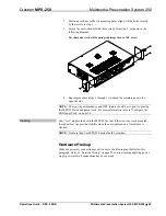
Position a rack ear so that its mounting holes align with the holes vacated
by the screws in step 1.
3.
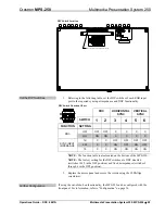
Secure the ear to the unit with three screws from step 1, as shown in the
following diagram.
Ear Attachment for Rack Mounting (this image shows a 1RU device)
4.
Repeat procedure (steps 1 through 3) to attach the remaining ear to the
opposite side.
NOTE:
The sync input impedance and DDC feature should be set prior to placing
the MPS-250 in an equipment rack. For more information, refer to “Configure the
RGB Input Ports” on page 28.
Stacking
Four “feet” are provided with the MPS-250 so that if the unit is not rack mounted,
the rubber feet can provide stability when the unit is placed on a flat surface or
stacked.
NOTE:
No more than two MPS-250 units should be stacked.
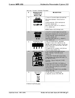
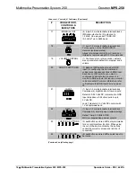
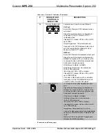
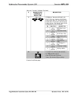
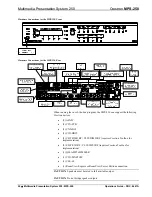
Hardware Hookup
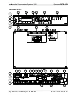
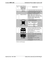
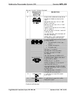
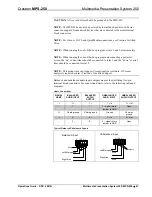
Make the necessary connections as called out in the illustrations that follow this
paragraph. Refer to “Network Wiring” on page 22 before attaching applying power.
Apply power after all connections have been made.
Operations Guide – DOC. 6647A
Multimedia Presentation System 250: MPS-250
•
25

