Multimedia Presentation System 250
Crestron
MPS-250
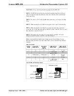
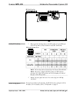
Typical Balanced/Unbalanced Outputs
Shield
AMP
Left
Right
+ -
G
+ -
Balanced Output
+
+
AMP
Left
Right
+ -
G
+ -
Unbalanced Output
+
+
Configure the RGB Input Ports
Each of the RGB input ports feature a set of six DIP switches located inside the
MPS-250. These switches are used to set the sync input impedance of each port and
simulate the presence of a monitor (DDC) for each RGB input.
The sync input impedance can be set to either 1k, 500, or 75 ohms. The setting from
the factory is 1k ohms and should work with most RGB sources. If the signal quality
is poor, lowering the input impedance to match the impedance of coax cable may
alleviate sync signal problems that are associated with RGB cables greater than the
typical VESA standard (typically six feet).
For laptops that require the presence of a monitor to enable its video output, the
MPS-250 has a selectable feature (DDC) that simulates the presence of a monitor so
RGB sources (such as a laptop computer) will transmit a signal even when an RGB
device is not connected to the MPS-250 output. Changing the DIP switch setting can
enable or disable this feature. The MPS-250 is shipped from the factory with the
DDC feature disabled.
NOTE:
The sync input impedance and DDC feature should be set prior to placing
the MPS-250 in an equipment rack.
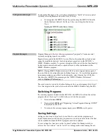
Find the DIP Switches
The DIP switches that configure the RGB input ports are located on the bottom of
the MPS-250. The only tools required are a #2 Phillips screwdriver and a grounding
strap (or grounded workstation).
CAUTION:
The MPS-250 contains ESD-sensitive devices. Perform the following
procedure while wearing a grounding strap that is properly grounded or on a
grounded workstation to avoid damaging the MPS-250.
1.
Connect RGB sources and a monitor to the MPS-250 as described in
“Hardware Hookup” on page 25.
2.
Remove the DIP switch access panel by removing the two screws located
on the bottom of the MPS-250. Use a #2 Phillips screwdriver to remove the
screws.
3.
Lift the access panel shown in the following diagram to expose the DIP
switches. Each RGB input port has a corresponding bank of DIP switches.
28
•
Multimedia Presentation System 250: MPS-250
Operations Guide – DOC. 6647A

