


Isys
®
12” Tilt Touch Screen
Crestron
TPMC-12
Connectors, Controls & Indicators
#
CONNECTORS
1
,
CONTROLS &
INDICATORS
DESCRIPTION
1 BUTTONS
2
(4) Backlit “hard key” buttons, programmable
(1) Miniature recessed hard reset button,
reboots the touch screen
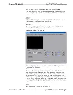
2
NET
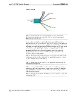
(1) 4-pin 3.5 mm detachable terminal block
Connects to Cresnet control network or
TPMC-CH-IMC interface module (included)
via 15 foot (4.6 meter) “triamese” cable
provided
24
: Power (24 Volts DC)
Y
: Data
Z
: Data
G
: Ground
3
GROUND
(1) 6-32 screw, chassis ground lug
4
USB
1
2
3
4
(2) USB Type A female
USB 2.0 ports for USB keyboard, mouse and
storage devices
3
5
MEMORY EXPANSION
(1) MMC compatible card slot
Accepts Multimedia Memory Cards (MMC)
up to 4 GB for memory expansion
3
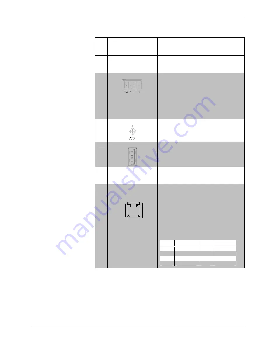
6
LAN
YELLOW/
GREEN
LED
GREEN
LED
PIN 8
PIN 1
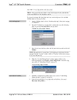
(1) 8-wire RJ-45 with two LED indicators
10BASE-T/100BASE-TX/1000BASE-T
Ethernet port
Left yellow LED indicates 10 Mbps link status
Left green LED indicates 100 Mbps link
status
Right green LED indicates 1000 Mbps link
status
For all LEDs, blinking = active,
on = no activity, off = no link
PIN
SIGNAL
PIN
SIGNAL
1
A +
5
C -
2
A -
6
B -
3
B +
7
D +
4
C +
8
D -
(Continued on following page)
10
•
Isys
®
12” Tilt Touch Screen: TPMC-12
Operations Guide – DOC. 6675C


