background image

Crestron 

QM-WMC


Wall Plate Media Center


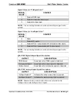
Signal Values for “VidInput Select” 

SIGNAL 

VALUE 

SOURCE 

Selects RGB input. 

Selects composite video input. 

Selects S-video input. 

NOTE:

  Use an Analog Initialize to send a decimal input signal to the 

symbol. 

Signal Values for “AudInput Select” 

SIGNAL 

VALUE 

SOURCE 

0 Mute 

Selects PC audio. 

Selects RCA 1 (associated with composite video input). 

Selects RCA 2 (associated with S-video input). 

NOTE:

  Use an Analog Initialize to send a decimal input signal to the 

symbol. 

QM-WMC Digital Output Signal Descriptions 

OUTPUT DESCRIPTION 

RGB Detect 

Goes high when RGB signal is detected. 

Composite Detect 

Goes high when video signal is detected. 

Svideo Detect 

Goes high when luminance signal is detected. 

QM-WMC Analog Output Signal Descriptions 

OUTPUT DESCRIPTION 

VidInput Select-F 

Indicates the video source that is selected. 

AudInput Select-F 

Indicates the audio source that is selected. 

NOTE:

  Returned values match values that were selected for the 

VidInput Select 

and 

AudInput Select 

inputs. 

Operations & Installation Guide - DOC. 6237A 

Wall Plate Media Center:  QM-WMC  

  33 

Summary of Contents for QM-WMC

Page 1: ...Crestron QM WMC Wall Plate Media Center Operations Installation Guide ...

Page 2: ...n by the Technical Documentation department at Crestron Electronics Inc 15 Volvo Drive Rockleigh NJ 07647 1 888 CRESTRON All brand names product names and trademarks are the property of their respective owners 2003 Crestron Electronics Inc ...

Page 3: ...tallation 22 Programming Software 26 Programming with SystemBuilder 28 Programming with SIMPL Windows 29 Programming with VisionTools Pro e 34 Example Program 34 Uploading and Upgrading 34 Communication Settings 35 Uploading a SIMPL Windows Program 38 Firmware Upgrade 39 Problem Solving 42 Troubleshooting 42 Further Inquiries 44 Future Updates 44 Return and Warranty Policies 45 Merchandise Returns...

Page 4: ......

Page 5: ...ith accompanying audio Auto detection of video signals provides feedback for operation of other system functions i e display operation Independent switching of audio and video signals allows audio program from one video source to run simultaneously with video program from another source Buffered computer output for connecting a local monitor QuickMedia port for simplified A V wiring and connection...

Page 6: ...ume Installing the optional QM WMIC Media Center Microphone Input into the QM WMC adds two Neutrik Combo microphone inputs with software enabled phantom power allowing microphone audio to be delivered simultaneous to the selected audio program Refer to the latest revision of the QM WMIC Operations Installation Guide Doc 6245 for more information Part Number Compatibility Due to production changes ...

Page 7: ...or conference room auditorium and lecture hall applications or anywhere else where audio video or computer equipment needs to be easily connected and disconnected from a presentation system or room control system The QM WMC allows users to bring their own A V devices to a wall plate in a presentation room while taking advantage of the auditorium s audio and video capabilities For more information ...

Page 8: ...r Crestron QM WMC The following block diagram represents the operation of the QM WMC with the optional QM WMIC Block Diagram of Wall Plate Media Center 4 Wall Plate Media Center QM WMC Operations Installation Guide DOC 6237A ...

Page 9: ...CUZ or later Front Connectors Computer Input 1 DB15HD female video sensing on H sync Computer Output 1 DB15HD female for monitor out Computer Audio 1 3 5mm mini jack computer soundcard type Composite Video 1 RCA yellow video sensing Composite Video Audio 2 RCA red and white S video 1 Mini DIN 4 pin video sense on luminance signal S video Audio 2 RCA red and white Rear Connectors QM WMC QuickMedia ...

Page 10: ...Hz 3 dB at unity gain Max Resolution Refresh Rate RGB 1600 x 1200 60 Hz vertical rate with CAT5 5E 6 cable length of 100 meters and skew rating 15 ns 100 meters3 H and V Sync RGB H 5 0 Vpp max into 1k ohms V 5 0 Vpp max into 2 2k ohms Audio Analog Digital Conversion Maximum line level input Input Impedance Bandwidth 24 bit 48 kHz 2 Vrms Video 1 Vrms PC 10k ohms 20 Hz to 20 kHz Operating Temperatur...

Page 11: ...ain areas of the site including the FTP site Physical Description Refer to the following illustrations The front of the QM WMC has connections for composite video RCA S video Mini DIN 4 pin and RGB DB15HD inputs as well as corresponding stereo inputs for each video source An additional DB15HD connector allows the hookup of an additional monitor LEDs on the front of the wall plate indicate power Cr...

Page 12: ...Wall Plate Media Center Crestron QM WMC QM WMC Shown with Optional QM WMIC 8 Wall Plate Media Center QM WMC Operations Installation Guide DOC 6237A ...

Page 13: ... 71 in 4 33 cm 1 64 in 4 18 cm 3 47 in 8 81 cm 2 10 in 5 34 cm 2 61 in 6 62 cm 2 14 in 5 45 cm NOTE 2 50 in 6 35 cm BACK BOX DEPTH REQUIRED QUICKMEDIA CONNECTOR Ports All user A V connections to the QM WMC are made through the ports on the front panel Network QM WMIC and QuickMedia connections Operations Installation Guide DOC 6237A Wall Plate Media Center QM WMC 9 ...

Page 14: ...ideo source to the presentation system A corresponding set of stereo RCA audio inputs red and white are provided for the video source s audio program This port can automatically detect the presence of a luminance video signal on pin 3 An LED indicates the presence of a luminance signal Refer to the following table for pin assignments S Video Pin Assignments PIN DESCRIPTION 1 Ground 2 Ground 3 Lumi...

Page 15: ...R This female connector is a buffered pass through port for connecting a secondary computer display to the computer s RGB video output Refer to the following table for pin assignments RGB DB15HD Pin Assignments PIN FUNCTION PIN FUNCTION 1 Red Video 9 No Connect 2 Green Video 10 Ground 3 Blue Video 11 No Connect 4 Reserved 12 No Connect 5 Ground 13 Horizontal Sync 6 Red Ground 14 Vertical Sync 7 Gr...

Page 16: ...ion refer to Network Wiring on page 14 QM 8 1 This eight pin RJ 45 transport port allows connection of the QuickMedia cable It carries audio video and microphone signals over CAT5E cable For more information on QuickMedia refer to QuickMedia Wiring on page 15 QM Pin Assignments PIN WIRE COLORS 568B DESCRIPTION 1 WHITE ORANGE RGB Red 2 ORANGE RGB Red 3 WHITE GREEN RGB Green 4 BLUE Digital Audio 5 W...

Page 17: ...s polled on the network Illumination indicates that the SIMPL Windows program currently loaded has a network device defined at the same Net ID as the QM WMC The LED flashes when communication with the processor occurs SETUP LED and Pushbutton The QM WMC is Touch Settable ID ready A SETUP pushbutton is concealed behind a Decora faceplate during normal use The SETUP pushbutton and its associated LED...

Page 18: ...ring diagram s appropriate for your specific system configuration available from the Downloads Product Manuals Wiring Diagrams section of the Crestron website www crestron com When calculating the wire gauge for a particular Cresnet run the length of the run and the power factor of each network unit to be connected must be taken into consideration If Cresnet units are to be daisy chained on the ru...

Page 19: ...Cresnet units strip the ends of the wires carefully to avoid nicking the conductors Twist together the ends of the wires that share a pin on the network connector and tin the twisted connection Apply solder only to the ends of the twisted wires Avoid tinning too far up the wires or the end becomes brittle Insert the tinned connection into the Cresnet connector plug and tighten the retaining screw ...

Page 20: ...equency compensation on each twisted pair video input to maintain high resolutions 1600 x 1200 with CRESCAT QM cable which contains both Cresnet and CAT5E wiring and most good quality CAT5E and CAT6 cables where skew rating is 15 ns 100 meters The total accumulated length of the cable determines the actual skew For example when connecting the QM WMC to a QM MD9x2 and then to the QM RMCRX the total...

Page 21: ... over the CAT5E wire Quick Media Video Signals on CAT5E NOTE When transmitting S video or composite video luminance uses the green video pathway chrominance uses the red video pathway and composite uses the blue video pathway The pin assignments for Crescat QM CAT5 CAT5E and CAT 6 wiring are based on the EIA TIA 568B RJ 45 Jack standard RJ 45 QuickMedia Connector Pin 1 Operations Installation Guid...

Page 22: ...ing a cable containing four wires is included for making Cresnet connections Identity Code All equipment and user interfaces within the network require a unique identity code Net ID These codes are two digit hexadecimal numbers from 03 to FE The Net ID of each unit must match an ID code specified in the SIMPL Windows program Refer to Setting the Net ID in Device Settings on page 31 for details of ...

Page 23: ...his method does not require that any devices be disconnected from the network Net IDs may be set with the entire Cresnet system intact This method requires the use of the Crestron Viewport version 3 35 or later Use the appropriate method to set the Net ID Method A Cresnet address settable ID 1 Ensure that the device requiring a Net ID change is the only unit connected to the control system 2 Open ...

Page 24: ...twork devices during the initial configuration of a Cresnet system or when such devices are being added replaced 1 Ensure that all network devices are connected to the control system 2 Open the Crestron Viewport version 3 35 or later 3 From the Viewport menu select Functions Assign Cresnet ID by Serial Number The Set Net ID by TSID window appears The window is first displayed with the data fields ...

Page 25: ... list CAUTION This function does not prevent you from setting duplicate IDs Be sure to check current assignments before entering the desired Cresnet ID number Serial Number to TSID Conversion This utility is useful in a case where there are multiple devices of the same type on a network you need to locate a particular one you know the TSID but not the serial number and your site installation list ...

Page 26: ...tallation NOTE If the QM WMIC is to be used refer to the installation instructions in the latest revision of the QM WMIC Operations Installation Guide Doc 6245 which can be downloaded from the Downloads Product Manuals section of the Crestron website www crestron com The following tools hardware are required for installation CRESCAT QM QuickMedia cable or equivalent not supplied terminated with RJ...

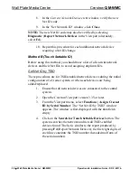
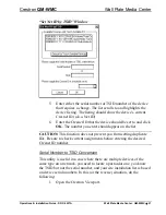
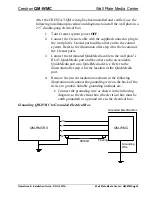
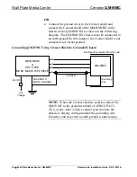
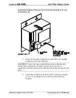
Page 27: ...plate s RJ 45 QuickMedia port and the other end to an available QuickMedia port on a QuickMedia device Refer to the illustration after step 4 for the location of the QuickMedia port 4 Remove the pre cut insulation as shown in the following illustration and connect the grounding wire on the back of the device to ground Suitable grounding methods are Connect the grounding wire as shown in the follow...

Page 28: ...ing QM WMC Using Cresnet Shield to Grounded Chassis QM RMCRX or CP2 CP2E MC2E MC2W MP2 MP2E QM WMC 24 G Z Y CHASSIS TO EARTH GROUND Grounding Wire SHIELD 24 VDC Line Voltage Electrical Box Isolated from Ground NOTE When the Cresnet shield is used to connect the QM WMC to the ground terminal of a PRO2 PAC2 AV2 or any other 2 Series control system where the chassis is already earth grounded the grou...

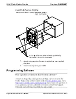
Page 29: ...l box CAUTION Excess wire that is pinched between the wall plate and electrical box could short out Make sure that all excess wire is completely inside the electrical box and not between the box and the wall plate 6 Attach the wall plate to the electrical box using the supplied 6 32 x L pan head screws as shown in the following diagram Operations Installation Guide DOC 6237A Wall Plate Media Cente...

Page 30: ...em power ON Programming Software Have a question or comment about Crestron software Answers to frequently asked questions FAQs can be viewed in the Online Help section of the Crestron website www crestron com Go to http www crestron com accounts login asp to post your own question or view questions you have submitted to Crestron s True Blue Support First time users will need to establish a user ac...

Page 31: ...temBuilder to create the final project files to be loaded into the panels Alternatively VT Pro e can be used to tweak projects created with the SystemBuilder or develop original touchpanel screen designs Once the program created by SystemBuilder is loaded into the control system Digital Media Tools DMT Software can be used to tune the system for optimal performance DMT software can be used to test...

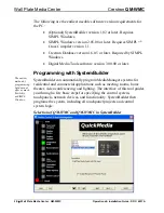
Page 32: ...he easiest method of programming but does not offer as much flexibility as SIMPL Windows SystemBuilder can automatically program MediaManager systems for residential and commercial applications such as meeting rooms home theater video conferencing and lighting The interface of this tool guides you through a few basic steps for specifying the control system touchpanels network devices and functiona...

Page 33: ... systems It provides a well designed graphical environment with a number of workspaces i e windows in which a programmer can select configure program test and monitor a Crestron control system SIMPL Windows offers drag and drop functionality in a familiar Windows environment NOTE The following assumes that the reader has knowledge of SIMPL Windows If not refer to the extensive help information pro...

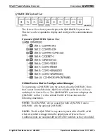
Page 34: ...dules QM Series folder of the Device Library and drop it in System Views The QM RMCRX system tree displays the QM WMC in Slot 5 with a default Net ID of 04 as shown in the following illustration NOTE The QM WMC device is used for both a QM WMC and a QM WMC with the optional QM WMIC NOTE The first QM WMC in a system is preset with a Net ID of 04 when its symbol is dragged into the upper pane of Sys...

Page 35: ...he QM WMIC when it is installed Setting the Net ID in Device Settings Double click the QM WMC icon in the upper pane to open the Device Settings window This window displays QM WMC device information The Net ID can be changed in this window using the Net ID tab as shown in the following figure QM WMC Device Settings Window Operations Installation Guide DOC 6237A Wall Plate Media Center QM WMC 31 ...

Page 36: ...WMC symbol in the SIMPL Windows Programming Manager The signals for the QM WMC are in Slot 1 of the QM WMC symbol Double click Slot 1 to view the symbol NOTE Slot 2 of the QM WMC symbol contains the symbol for the QM WMIC For more information on the QM WMIC symbol refer to the latest revision of the QM WMIC Operations and Installation Guide Doc 6245 which can be downloaded from the Downloads Produ...

Page 37: ...g Initialize to send a decimal input signal to the symbol QM WMC Digital Output Signal Descriptions OUTPUT DESCRIPTION RGB Detect Goes high when RGB signal is detected Composite Detect Goes high when video signal is detected Svideo Detect Goes high when luminance signal is detected QM WMC Analog Output Signal Descriptions OUTPUT DESCRIPTION VidInput Select F Indicates the video source that is sele...

Page 38: ...grades are available from the Crestron website as new features are developed after product releases In those instances one has the option to upload via the programming software or to upload and upgrade via the Crestron Viewport NOTE The Crestron Viewport is available as a pull down command from SIMPL Windows and VT Pro e Tools Viewport or as a standalone utility The Viewport utility performs multi...

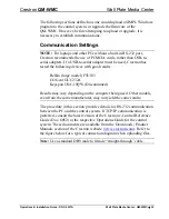
Page 39: ... Keyspan USA 19QW Discontinued Results may vary depending on the computer being used Other models even from the same manufacturer may not yield the same results The procedure in this section provides details for RS 232 communication between the PC and the control system If TCP IP communication is preferred consult the latest version of the Crestron e Control Reference Guide Doc 6052 or the respect...

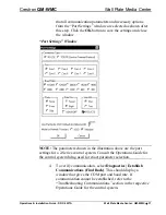
Page 40: ...elect Tools Viewport 2 Refer to the figure after this step From the Viewport menu select Setup Communications settings alternatively press Alt D to open the Port Settings window Setup Communications Settings Command 3 Select RS 232 as the connection type Verify that an available COM port COM 1 is shown after this step is selected and 36 Wall Plate Media Center QM WMC Operations Installation Guide ...

Page 41: ... port settings for a 2 Series control system Consult the Operations Guide for the control system being used for exact parameter selection 4 To verify communication select Diagnostics Establish Communications Find Rack This should display a window that gives the COM port and baud rate If communication cannot be established refer to the Troubleshooting Communications section in the respective Operat...

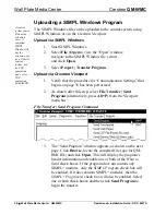
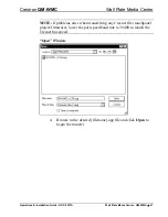
Page 42: ...rocedure for Communication Settings that begins on page 35 has been performed 2 As shown after this step select File Transfer Send Program alternatively press Alt P from the Viewport menu bar File Transfer Send Program Command 3 The Send Program window appears as shown on the next page Click Browse locate the compiled file spz for QM RMCRX and click Open This will display the program s header info...

Page 43: ...rol system Firmware Upgrade A firmware upgrade file has the extension csf To take advantage of all the QM WMCs features it is important that the unit contains the latest firmware available Please check the Crestron website http www crestron com downloads software_updates asp for the latest version of firmware Not every product has a firmware upgrade but as Crestron improves functions adds new feat...

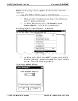
Page 44: ... on page 35 has been performed 2 As shown after this step select File Transfer Load Network Device from the Viewport menu bar File Transfer Load Network Device Command 3 As shown in the Select Network ID window select the Net ID of the QM WMC and then click OK The Open window appears refer to the following graphics Select Network ID Window 40 Wall Plate Media Center QM WMC Operations Installation ...

Page 45: ... any Cresnet file touchpanel project firmware lower the port speed baud rate to 38400 to match the Cresnet bus speed Open Window 4 Browse to the desired filename upg file and click Open to begin the transfer Operations Installation Guide DOC 6237A Wall Plate Media Center QM WMC 41 ...

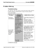
Page 46: ...ified in SIMPL Windows Verify SIMPL Windows program for setting Net ID Wall plate is not functioning QM WMC Net ID is the same as another device s Net ID Assign a different Net ID for the QM WMC to match the Net ID specified in the SIMPL Windows program Source LEDs do not light Sources are not transmitting signals Verify source operation Incorrect peak setting Adjust QM RMCRX peak control until au...

Page 47: ...TION Poor RGB or video image quality Incorrect peak and or boost setting Adjust QM RMCRX peak or boost controls until image quality is improved For more information refer to the latest revision of the QM RMCRX Operations and Installation Guide Doc 6236 Operations Installation Guide DOC 6237A Wall Plate Media Center QM WMC 43 ...

Page 48: ...u can also log onto the online help section of the Crestron website www crestron com to ask questions about Crestron products First time users will need to establish a user account to fully benefit from all available features Future Updates As Crestron improves functions adds new features and extends the capabilities of the QM WMC additional information may be made available as manual updates Thes...

Page 49: ...ps are not covered This warranty extends to products purchased directly from CRESTRON or an authorized CRESTRON dealer Purchasers should inquire of the dealer regarding the nature and extent of the dealer s warranty if any CRESTRON shall not be liable to honor the terms of this warranty if the product has been used in any application other than that for which it was intended or if it has been subj...

Page 50: ...Wall Plate Media Center Crestron QM WMC 46 Wall Plate Media Center QM WMC Operations Installation Guide DOC 6237A This page is intentionally left blank ...

Page 51: ...Crestron QM WMC Wall Plate Media Center Operations Installation Guide DOC 6237A Wall Plate Media Center QM WMC 47 This page is intentionally left blank ...

Page 52: ...restron Electronics Inc Operations Installation Guide DOC 6237A 15 Volvo Drive Rockleigh NJ 07647 06 04 Tel 888 CRESTRON Fax 201 767 7576 Specifications subject to www crestron com change without notice ...

Reviews: