Crestron
ST-PC
Dual AC Power Control
Module
NOTE:
Crestron software and any files on the website are for Authorized Crestron
dealers and Crestron Authorized Independent Programmers (CAIP) only. New users
may be required to register to obtain access to certain areas of the site (including the
FTP site).
Physical Description
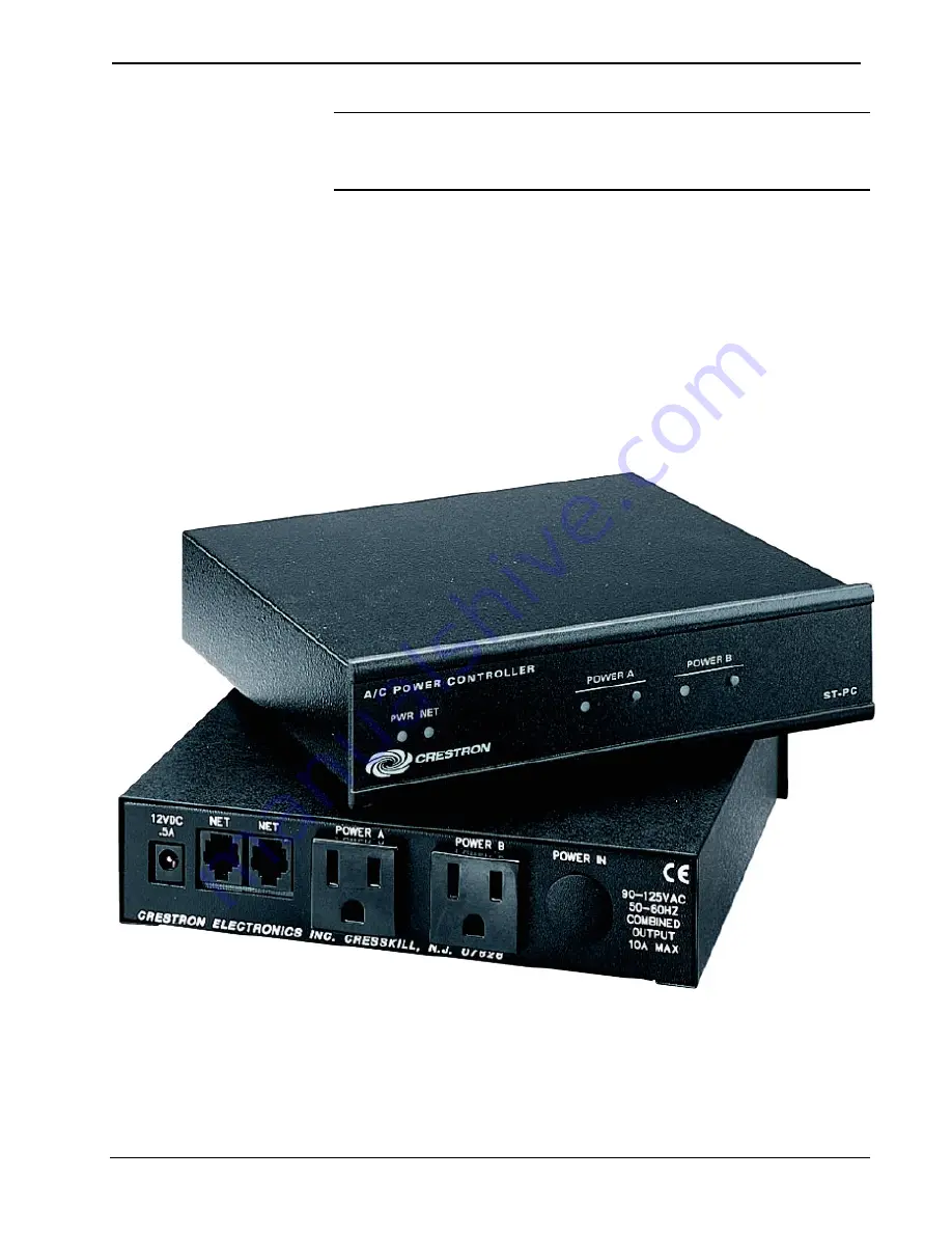
The ST-PC, shown in the following illustrations, is housed in a black enclosure with
labels on the front and rear panels. There are four LEDs on the front panel that
indicate the unit’s current status. There are also two momentary pushbutton switches
that are used to toggle the relay states. The two switches are located to the right of
the POWER A/B LEDs on the front panel. All connections are made on the back of
the unit. The proper domestic and international power cords and plugs are used on
the ST-PC and STI-PC, respectively. Refer to the physical views shown below.
There are four rubber feet on the base of the unit for stability and to prevent
slippage.
ST-PC Front and Back Views
Operations Guide – DOC. 5708A
Dual AC Power Control Module: ST-PC
•
3


