Crestron
TPS-4500IMW
Wall-Mounted Interface Module
•
COMP Y and C
– These two (four-pin) ports on the back of
the unit provide connection for a video source. The unit can
accept either a single signal over one wire (composite video or
COMP
) or two separate signals: one for brightness (luminance
or
Y
), and the other for color (chrominance or
C
). The port is
made active with the purchase and installation of the TPS-VID,
composite and S-video input TV video card, into the
touchpanel. Consult the latest revision of the TPS-VID
Operations & Installation Guide (Doc. 5869) for details.
NOTE:
Except for differential input (balanced) video signal, the two
(four-pin) video connectors with jumpers should be installed at all times.
Refer to "Hardware Hookup" on page 5 for jumper details.
•
NET
– This four-pin connector is used to connect to other
four-wire devices in the Cresnet system. If making network
connections to Cresnet peripherals, refer to "Network Wiring"
on page 4 for details.
•
NET/VIDEO
– This 10-position RJ45 mates with the
TPS-4500 touchpanel and has a dual purpose. Refer to the
descriptions and pinout table that follow this paragraph.
1. This port provides network and power connection to the
touchpanel.
2. This port also makes available composite or S-video input for
TV video card (with the purchase and installation of the
TPS-VID). Consult the latest revision of the TPS-VID
Operations & Installation Guide (Doc. 5869) for details.
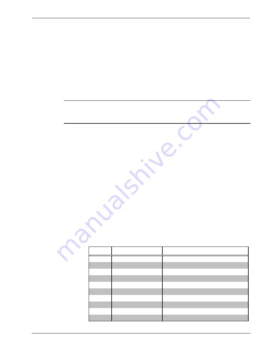
NET/VIDEO Pinouts
PIN #
DESIGNATION
DESCRIPTION
1
+24V
Power (Network)
2
GND
Ground (Network)
3
C+
Chrominance (Positive)
4
C-
Chrominance (Negative)
5
Y
Data (Network)
6
Z
Data (Network)
7
Y+
Luminance (Positive)/Composite
8
Y-
Luminance (Negative)/Composite
9
GND
Ground (Network)
10
+24V
Power (Network)
Operations Guide - DOC. 5913
Wall-Mounted Interface Module: TPS-4500IMW
•
3


