
DO
GUIDE
DO
Check the Box
QUANTITY
PRODUCT
PART NUMBER
1
Bit, Torx
®
, T15
2043927
1
Connector, 2-Pin
2003574
4
Screw, 6-32 x 3/8", Pan Head, Phillips
2007231
6
Screw, 6-32 x 1-1/2", Pan Head, Phillips
2007254
4
Screw, 10-32 x 3/8", Pan Head, Phillips*
2007290
4
Screw, M4 x 8 mm, Pan Head, Phillips
2041962
4
Washer, Lock, M4, 7.6 mm OD, 4.1mm ID, 0.9 mm TH
2041964
* For future use
TSD-2020-WMK-BB
Wall Mount Kit and Back Box for TSD-2020
DO
Prepare for Back Box Installation
The Crestron
®
TSD-2020-WMK-BB is a UL
®
listed, recessed, and wall-mounted metal back box for the TSD-2020 V-Panel
®
20" HD Touch Screen Display
(sold separately). Conduit knockouts are provided on the top and bottom.
Prepare for back box installation by completing the steps below.
CAUTION:
Allow an air gap of at least 12" (305 mm) in the wall cavity above and below the installation location for heat dissipation.
NOTE:
The type of installation may create the need for forced ventilation.
NOTE:
The knockout holes on the back box are intended for Class 2 wiring only. Remove the appropriate knockouts before installation.
1. Install the TSD-2020-PMK (sold separately) in the desired location. Refer to the TSD-2020-PMK documentation for installation instructions.
2. Remove the seven 06-32 x 3/8" Torx type security screws that attach the back box cover to the front of the back box. There are three screws across
the top and two on each side. Then, remove the back box cover. Save the seven screws as they will be reinstalled at the end of the
TSD-2020-WMK-BB installation procedure.
CAUTION:
Use a 24 Vdc supply to power the unit. Using a supply with a higher voltage will damage the unit.
3. Run 24 Vdc and DigitalMedia™ cables into the back box through the knockout holes.
DO
Install the Back Box and Mount the Display
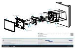
NOTE:
Refer to the illustration on the back of this document for the following steps.
1. Attach the back box to the TSD-2020-PMK using the six included 06-32 x 1-1/2" screws.
NOTE:
In addition to the six holes used in this step, the back box also has holes on both sides that can be used to reinforce the installation. Use
standard drywall screws or nails (not supplied) to attach the sides of the back box to studs. Use care when attaching the right side of the back box to
a stud in order to avoid damaging the printed circuit board in the back box.
2. Attach the mounting bracket that ships with the DM-RMC-SCALER-C (sold separately) to the standoffs in the back box using the four included 06-32
x 3/8" screws.
3. Route the DigitalMedia cable behind the mounting bracket, and connect it to the DM IN port on the DM-RMC-SCALER-C.
4. Attach the DM-RMC-SCALER-C to the mounting bracket using the four 06-32 x 1" screws that ship with the DM-RMC-SCALER-C.
5. Attach the TSD-2020 display to the back box cover using the four included M4 x 8 mm screws and the four included M4 washers.
6. Hang the assembly from step 5 on the back box by engaging the two slots on the bottom of the back box cover with the two hinges on the bottom
of the back box. When the assembly is engaged, the opening in the back box cover will face upward, allowing access to the connector ports on the
back of the TSD-2020.
DO
Complete the Wiring
1. Attach the 24 Vdc cable coming in through the knockout to the 24VDC IN port on the printed circuit board inside the back box.
2. Attach the built-in cable from the 24VDC OUT port on the printed circuit board inside the back box to the 24 V 0.75A MAX port on the
DM-RMC-SCALER-C.
3. Attach the built-in cable from the 19VDC OUT port on the printed circuit board inside the back box to the DC-IN 19V port on the back of the
TSD-2020.
4. Use the HDMI
®
interface cable included in the back box to connect the HDMI OUT port on the DM-RMC-SCALER-C to the HDMI port on the
TSD-2020.
5. Use the USB type A to micro-USB type B cable included in the back box to connect the USB HID port on the DM-RMC-SCALER-C to the
Micro-USB port on the TSD-2020.
DO
Complete the Installation
Complete the installation by swinging the TSD-2020 and back box cover upward on the back box hinges so the TSD-2020 and back box cover are
vertically oriented and closing the back box. Secure the assembly in this position using the seven Torx screws from step 2 of “DO Prepare for Back Box
Installation” above.


