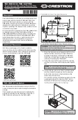

4. Reach into the TSW-UMB-60 assembly and push
the rear half back to ensure it is fully behind the
mounting surface. Ensure the front of the
TSW-UMB-60 assembly is level.
For portrait mounting, allow the bracket to angle
into the opening (left side first) before tightening.
Pushing the Rear Half Behind the Mounting Surface
Push the top surface
downward to install
the bottom half first.
TSW-UMB-60
Loosen both
of the screws.
5. Tighten the two screws to complete the
installation.
Completing the Assembly
Push the rear half
back.
Ensure the front
is level, and then
tighten both screws.
TSW-UMB-60/-560P-PMK Installation
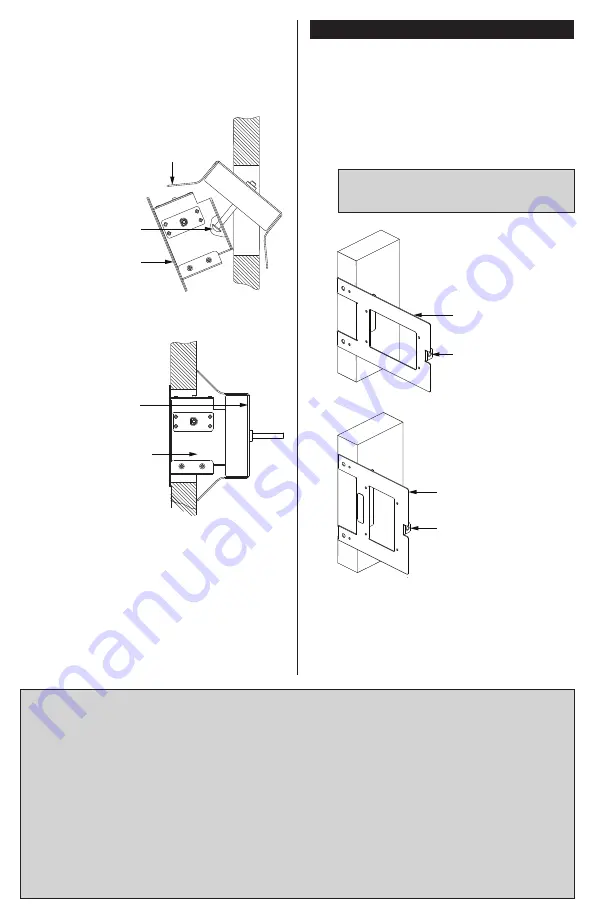
The TSW-UMB-60-PMK supports preconstruction and
postconstruction mounting applications for the
TSW-560, TSW-760, and TSW-1060 touch screens,
while the TSW-UMB-560P-PMK supports
preconstruction and postconstruction mounting
applications for the TSW-560P portrait touch screen.
• For preconstruction applications, use standard
drywall nails or screws to attach the PMK to a
wall.
CAUTION
: Allow an air gap of at least
12" (305 mm) in the wall cavity above and below
the TSW-UMB-60 for heat dissipation.
Attaching the TSW-UMB-60-PMK to a Wall
• For postconstruction applications, use the PMK
as a cutout template by turning it to face the wall,
ensuring it is level, and temporarily tacking it to
the wall with finishing nails in the smaller holes
around the cutout opening. Trace the cutout
opening with an appropriate drywall saw.
TSW-UMB-60-PMK
Use a tie wrap to hold
the cable until the touch
screen is mounted.
Use a tie wrap to hold
the cable until the touch
screen is mounted.
TSW-UMB-560P-PMK
Attaching the TSW-UMB-560P-PMK to a Wall
Product warranty can be found at
www.crestron.com/warranty.
The specific patents that cover Crestron products are listed at
patents.crestron.com.
Certain Crestron products contain open source software. For
specific information, please visit
www.crestron.com/opensource.
Crestron and the Crestron logo are either trademarks or
registered trademarks of Crestron Electronics, Inc. in the
United States and/or other countries. Other trademarks,
registered trademarks, and trade names may be used in this
document to refer to either the entities claiming the marks
and names or their products. Crestron disclaims any
proprietary interest in the marks and names of others.
Crestron is not responsible for errors in typography or
photography.
This document was written by the Technical Publications
department at Crestron.
©2017 Crestron Electronics, Inc.
Crestron Electronics, Inc.
Installation Guide
15 Volvo Drive
DOC. 7911B
Rockleigh, NJ 07647
(2047690)
Tel: 888.CRESTRON
03.17
Fax: 201.767.7576
Specifications subject to
www.crestron.com
change without notice.


