background image

Crestron 

WPR-48 

Waterproof Wireless Handheld Remote


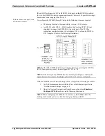
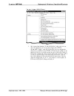
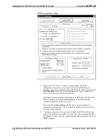
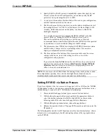
6.  Specify the RF or the IR gateway compatibility options that apply to your 

Cresnet system. For an RF configuration, you can also specify the RF 
power level as a percentage from 1% to 100%. 

7.  As you select the number of buttons that will be used in your configuration, 

note the limitations stated on the screen. 

8. The 

Miscellaneous Settings

 area lets you set the relative brightness level of 

the backlight (from 1% to 100%), set the timeout for the backlight (1-999 
seconds), which reduces wear on the battery, or choose to disable the 
backlight completely.  
 
You can also choose to allow changing the RF ID or IR ID via button 
presses. (Refer to “Setting RF/IR ID via Button Presses” below.)  
This can be useful when first setting up a job. However, Crestron 
recommends that you disable this option when the WPR-48 will be operated 
by an end user, to avoid accidental changes to the ID settings.  

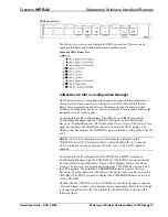
9. The 

Information from WPR48

 area displays the WPR-48 firmware version 

and the battery’s charge level (as a percentage value). This area also 
displays communications status messages. 

10.  The three buttons at the bottom of the screen are used to send the screen 

settings to the device, to save the settings to a file, or to exit the 
configuration setup operation. 
 
If you select the 

Save To File

 button, the saved file can be used to upload 

directly to the remote via the Viewport 

File Transfer | Update WPR-48 

Firmware

 function. This can be useful if you are preparing files in the 

office to be sent to an installation site. 

NOTE: 

Do not remove the WPR-48 from the docking station until you have exited 

the configuration operation. If you do, the backlight timeout function may be 
disabled, which would result in excessive wear and tear on the battery. 

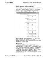
Setting RF/IR ID via Button Presses 

If you have checked 

Allow key presses to change unit’s RF or IR ID 

on the “WPR48 

Configuration” window, you can use a special button sequence to alter these values 
without having to connect to a PC. Perform the following steps. 

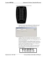
1.  Press and hold both page buttons (press center of bottom button). 

2.  While holding the page buttons, press and hold the appropriate button to 

select the desired operation (Set IR ID or Set RF ID), as shown in the 
following table. This will cause both page LEDs to illuminate. 

3.  While holding the operation button, release the page buttons. 

4.  Release the operation button. (The page LEDs remain on until you enter the 

ID number.) 

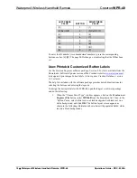
The following table lists the two ID functions as well as hexadecimal values, shown 
in brackets [ ], corresponding to the left and right positions of the top eight buttons 
on the WPR-48 

Operations Guide – DOC. 6254A 

Waterproof Wireless Handheld Remote: WPR-48  

  9 

Summary of Contents for WPR-48

Page 1: ...Crestron WPR 48 Waterproof Wireless Handheld Remote Operations Guide...

Page 2: ...arranty WARNING After installing button labels as described in this Operations Guide tighten all eight screws that secure the rear cover to the button faceplate evenly just until the gasket is no long...

Page 3: ...intable Customized Button Labels 10 Installing Replacing Button Labels 12 Installing Alternate Foot 13 Programming the WPR 48 14 Earliest Version Software Requirements for the PC 14 Programming with S...

Page 4: ......

Page 5: ...ate use under any lighting conditions The WPR 48 can communicate via RF or IR with a number of gateways in a Crestron control system Cresnet system Since it is compatible with Crestron s CNRFGWA and C...

Page 6: ...evice controller 3 The latest versions can be obtained from the Downloads Software Updates section of the Crestron website www crestron com Refer to NOTE after last footnote 4 Crestron 2 Series contro...

Page 7: ...ximum duration of 30 minutes per IEC 60529 IPX7 standards Exceeding these limits may result in damage to the equipment possible personal injury and void the product warranty The unit is shipped with t...

Page 8: ...ndows program based on the application of the unit within the Cresnet system Indicators The only indicators on the hand held WPR 48 are the four LEDs on the face of the unit above the button function...

Page 9: ...the equipment off and on the user is encouraged to try to correct the interference by one or more of the following measures Reorient or relocate the receiving antenna Increase the separation between...

Page 10: ...adapter Refer to the following illustration NOTE Check the SIMPL Windows gateway models prior to setting the RF ID or IR ID Some gateway models do not support ID 00 or FF NOTE If the battery in the W...

Page 11: ...ill function The settings are not transferred to the device until that instruction is given When the window is first opened it displays the values currently in the connected device If there is no devi...

Page 12: ...the RF configuration are RF Remote RF ID 10 433 MHz 27 Buttons 100 Backlight Brightness 10 second Backlight Timeout unchecked Allow key presses If you select Load From Device and the device contains...

Page 13: ...the configuration setup operation If you select the Save To File button the saved file can be used to upload directly to the remote via the Viewport File Transfer Update WPR 48 Firmware function This...

Page 14: ...n labels Also requires Crestron Database version 16 3 or later The help file included with the software package provides detailed instructions for selecting the buttons and entering the legends To des...

Page 15: ...or nine characters in wider fields An error message appears if you try to enter too many characters You can select any of the three fonts available from the drop down list Arial Crestron Transport or...

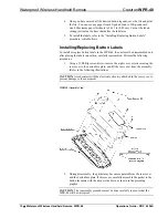
Page 16: ...arefully reassembled Perform the following procedures 1 Using a 1 Phillips screwdriver remove the eight cover screws securing the rear cover to the button faceplate and lift the rear cover from the as...

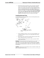
Page 17: ...the alternate blank foot supplied refer to the following illustration and perform the associated procedures 1 Using a 1 Phillips screwdriver remove the two pan head Phillips screws securing the lanya...

Page 18: ...1 Crestron Database version 16 2 3 or later Required by SIMPL Windows and Crestron Engraver Viewport version 3 99 01 or later For setting up the unit configuration Crestron Engraver version 2 2 Requir...

Page 19: ...lays the CNRFGWA gateway in Slot 9 with a default Net ID of 24 NOTE The ST CP control processor is automatically configured with a CNRFGWA in its STCP Net Device Slot 3 with a fixed Net ID of 2 when t...

Page 20: ...s Wireless Remotes IR folder of the Device Library and drop it on the CNXRMIRD symbol in System Views The CNXRMIRD then displays the WPR 48 with the transmitter s default RF IR ID 0F Pro2 System Tree...

Page 21: ...n four different modes All four modes are configurable using the Crestron Viewport 48 button mode In 48 button mode each of the top eight pushbuttons can trigger up to three functions depending on whe...

Page 22: ...programmers to installers from Crestron to dealers etc Even firmware upgrades are available from the Crestron website as new features are developed after product releases In those instances one has th...

Page 23: ...ntacts of the WPR DS During a firmware upload procedure the charging circuits are automatically disconnected Typical Connection Diagram when Uploading Firmware from the PC 1 Open the Crestron Viewport...

Page 24: ...has been performed 2 Press one of the buttons on the WPR 48 to activate the unit The backlight should come on NOTE Be aware that pressing a button to activate the unit automatically sends whatever co...

Page 25: ...y charge is low Place unit in docking station to recharge battery Intermittent response during RF transmission RF gateway is near large metal structure Verify that large amount of metal is not blockin...

Page 26: ...the online help section of the Crestron website www crestron com to ask questions about Crestron products First time users will need to establish a user account to fully benefit from all available fea...

Page 27: ...t lamps are not covered This warranty extends to products purchased directly from CRESTRON or an authorized CRESTRON dealer Purchasers should inquire of the dealer regarding the nature and extent of t...

Page 28: ...Crestron Electronics Inc Operations Guide DOC 6254A 15 Volvo Drive Rockleigh NJ 07647 10 04 Tel 888 CRESTRON Fax 201 767 7576 Specifications subject to www crestron com change without notice...

Reviews: