background image


Chapter Three - 28 

Managing Power 

Battery Charging Notice 

   
The  followings  are  the  detailed  information  for  charging  the  Primary  and 
Secondary batteries under AC and DC modes: 
 

AC mode:   


When the Power Status is changed and AC mode is detected, the Primary 
battery will be charged.     


Until  the  Primary  Battery  is  finished  charging,  then  it  will  continue  to 
charge the Secondary Battery fully also.   


If there is no Power Status change, until the capacity is down below 90%, 
a natural discharging occurs, and then recharge again. 


DC mode:   


When DC mode is detected, it will discharge the Secondary Battery until 
the  capacity  is  below  10%,  and  then  switch  to  the  Primary  Battery  for 
continuing discharging.   


When the capacity of the Primary Battery is below 10%, the Low Battery 
LED will flash. 


  Caution: 

For  the  system  safety  issue, battery  charger  circuit  design will  stop 
charging  battery  automatically  while  battery  internal  temperature is 
detected over 60 degree.


Summary of Contents for RK9

Page 1: ...NOTEBOOK COMPUTER RK9 User s Guide...

Page 2: ...his manual is sold or licensed as is Should the programs prove defective following purchase the buyer and not the manufacturer its distributor or its dealer assumes the entire cost of all necessary se...

Page 3: ...ext power Joe Chang Source is required when operating at 20 Add HDD password function Add DockUnder DUK89 DUT89 PCI card PCI express Card slot info Update BIOS screen and add serial port setting info...

Page 4: ...d on the user is encouraged to try to correct the interference by one or more of the following measures Re orient or relocate the receiving antenna Increase the separation between the equipment and re...

Page 5: ...e equipment The manufacturer is not responsible for any radio or television interference caused by unauthorized modification of this device or the substitution of the connecting cables and equipment o...

Page 6: ...61000 4 2 EN61000 4 3 EN61000 4 4 EN61000 4 5 EN61000 4 6 EN61000 4 8 EN61000 4 11 EN61000 3 2 EN61000 3 3 Generic Immunity Standard LVD EN 60950 1 2006 A11 2009 IEC 60950 1 2005 R TTE CE Manual Regul...

Page 7: ...EC Low voltage Directive 2006 95 EC the Amendment Directive 93 68 EEC and the procedures given in European Council Directive 99 5 EC and 2004 108 EC The equipment was passed and the equipment test wa...

Page 8: ...third prong is an important for safety Do not neglect the importance for it If you are not able to access a compatible outlet installing one by a qualified electrician is necessary When unplugging the...

Page 9: ...eplacement please contact with to your service representative or qualified service personnel Please dispose of a damaged battery promptly and carefully Explosion or leakage may occur if the battery is...

Page 10: ...pressure on the natural you are encouraged to use the appropriate take back for reusing or recycling most of the materials in a safe way after the service life The crossed bin symbol indicates proper...

Page 11: ...PTICAL DISK DEVICE ODD 12 EXPRESS AND PC CARDS 13 RTC 13 REPLACING MODULES 14 WIRELESS DEVICES OPTIONAL 15 INVISIBLE MODE OPTIONAL 22 DOCKUNDER DUK89 OPTIONAL 23 CHAPTER THREE MANAGING POWER 26 AC ADA...

Page 12: ...AL 48 CHAPTER SIX SPECIFICATIONS 49 CPU 49 MEMORY 49 CHIPSET 49 DISPLAY 49 KEYBOARD 49 TOUCHPAD 50 HARD DISK DRIVE HDD 50 OPTICAL DISK DRIVE ODD 50 I O PORTS 50 AC ADAPTER 51 BATTERY 51 SYSTEM UNIT DI...

Page 13: ...ROTECTOR SP 200 55 DUAL BATTERY CHARGER RT202D 55 COM 3 4 CARD AND ADDITIONAL SERIAL PORTS 55 MILITARY CONNECTOR MILITARY SERIAL CONNECTOR 55 DOCKUNDER DUK89 55 TRUST PLATFORM MODULE TPM 56 CHAPTER EI...

Page 14: ...g The following components are along with your computer If there is any missing or damaged please notify the dealer immediately Computer Unit Removable HDD Hard Disk Drive Removable ODD Optical Disk D...

Page 15: ...cally Under an emergency situation it is able to skip heating for booting up the system immediately by pressing the power switch for 9 seconds The speaker will also beep with a special sound It is not...

Page 16: ...nnas Optional WLAN R HSDPA UMTS 3 LED Indicators and Power Switch 4 Touchpad 5 Touchpad Right and Left Button 6 External GPS SMA Antenna Optional Heater HDD in Use BT WLAN GPS Secondary Battery Chargi...

Page 17: ...Chapter One 4 Getting Started Right View 1 Flex Bay a Standard SATA ODD Optical Disk Drive b Optional 2nd HDD or 2nd Battery 2 SATA HDD Hard Disk Drive 1 2...

Page 18: ...Wire 4 USB Port Universal Serial Bus 5 USB Port Universal Serial Bus 6 USB Port Universal Serial Bus 7 External Speaker Earphone Jack 8 Line in Jack 9 Microphone Jack 10 Express Card Slot x 1 PC Card...

Page 19: ...View 1 Optional Military Connector Port 2 Optional Military Connector Port 3 DC Power Jack 4 Serial Port DB9 COM1 Default RS232 5 RGB Port 6 Docking Port 7 Printer Port 8 Serial Port DB9 COM2 Default...

Page 20: ...Chapter One 7 Getting Started Bottom View 1 Primary Battery 2 ODD Latch 3 HDD Latch 1 2 3...

Page 21: ...nly Please keep the keyboard facing up i e normal operating direction to maintain water resistance NEVER immerse the unit in water or spray water at an upside down system Doing so may cause permanent...

Page 22: ...becomes lower the heater will heat up again to maintain the temperature set by user The function will be different from the way you use with the power button 1 Press 12 seconds and release USB port is...

Page 23: ...in all you need to press any key Hibernate Under Hibernate mode the system will save your work into HDD You are able to do enter Hibernate mode by directly clicking from your OS Or you can do the Hibe...

Page 24: ...the main keyboard with the numeric figures printed on the upper right of their respective keys There are keys for the digits 0 9 the decimal point addition subtraction multiplication and division in...

Page 25: ...e CD R Photo CD multiple session compatible Video CD CD EXTRA CD RW CD TEXT and etc Caution Do not use the IDE interface ODD it may cause the computer malfunction The following procedure assumes that...

Page 26: ...II cards To remove the card push the button on the right of the card to eject it The ejecting button can hide into the compartment by pushing it inward gently RTC Battery backed up RTC Real Time Cloc...

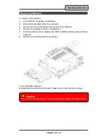
Page 27: ...turn and loose the screws on the modules 4 Remove the battery from the compartment 5 Push the latch knob to release the ODD or HDD module and push them outward 6 Remove the module from the computer To...

Page 28: ...h WWAN GPS and taking the systems working under Windows 7 64 bit OS for example Wireless LAN 1 Driver Application Installation a Install the Chipset Driver first b Then install the Wireless Manager 2...

Page 29: ...n install the Wireless Manager 2 Launch the Wireless Manager a Launch the Wireless Manager b Click Bluetooth for enabling the Bluetooth function click again for disabling the Bluetooth function Once t...

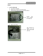
Page 30: ...M card a Turn off your computer b Reverse your computer to the bottom side c Find the battery bay and loosen the screw besides it d Remove the battery Loosen the screw besides the battery bay After re...

Page 31: ...r Two 18 Operating Information e Slide the SIM card lock to the left to open f Pull up the SIM card slot g Put your SIM card into the SIM card slot h Push down the SIM card slot Pull up the SIM card t...

Page 32: ...b Then install the Wireless Manager 3 Launch the Wireless Manager a Launch the Wireless Manager b Click WWAN for enabling the WWAN function click again for disabling the WWAN function Once the WWAN st...

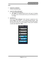
Page 33: ...again for disabling the GPS function Once the GPS starts up the RF LED will turn on accordingly 3 Update Driver Enter into the Device Manager in My Computer to update driver then select Browse my com...

Page 34: ...Fly Mode You are able to turn off all the Wireless Devices without doing any software settings The system will auto run the Wireless Manager while booting There are two ways to turn on the Wireless M...

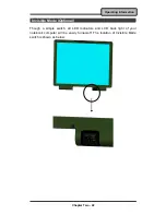
Page 35: ...Operating Information Invisible Mode Optional Though a simple switch all LED indicators and LCD back light of your notebook computer will be easily turned off The location of Invisible Mode switch is...

Page 36: ...ttaches directly to DockUnder and automatically charges the computer while docked Ports 1 Serial Port DB9 COM2 Default RS232 2 Serial Port DB9 COM1 Default RS232 3 USB 1 2 4 Antenna Hole Reserved 5 RG...

Page 37: ...pen the rubber cap of the docking connector 3 Align the docking connector 4 Loosen the bolts 5 Push the computer horizontally to join the guiding pins 6 Pull the metal bar outwards 7 Pull up the metal...

Page 38: ...e power of DockUnder with the Key that can use all the functions on DockUnder Meantime Computer will also have the power There are 2 PCI slots and 1 PCIe slot on the DockUnder Maximum card dimensions...

Page 39: ...usively for the computer Having other appliances on the same line may cause interference Use a power strip with built in surge protection Connecting the AC adapter Plug the AC cord to the adapter Plug...

Page 40: ...e Battery Plug in the AC adapter or optional vehicle adapter to start the battery charging If the battery is already full the sense circuitry will stop high current charge within several minutes There...

Page 41: ...attery fully also If there is no Power Status change until the capacity is down below 90 a natural discharging occurs and then recharge again DC mode When DC mode is detected it will discharge the Sec...

Page 42: ...wer Options Lower the intensity of the display by brightness control Use standby option when computer is temporarily not in use Shut down the computer when it will not be for a long time use Replacing...

Page 43: ...Interface for power management With ACPI and an ACPI compliant operating system such as Windows the feature will allow you to reduce the power consumption for energy saving By supporting ACPI the AC...

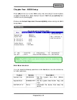
Page 44: ...SATA Port 2 Auto System Memory 632 KB Extended Memory 1012736KB Item Specific Help Tab Shift Tab or Enter selects field F1 Help Select Item Change Values F9 Setup Defaults Esc Exit Menu Enter Select...

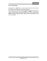
Page 45: ...d keys and functions for setup The scroll bar on the right of any window indicates that there is more than one page of information in the window Use PgUp and PgDn to display all the pages Pressing Hom...

Page 46: ...r you enter parameters of hard disk drive installed at this connection Auto autotypes hard disk drive installed here CD ROM a CD ROM drive is installed here ATAPI Removable removable disk drive is ins...

Page 47: ...g Disabled User you enter parameters of hard disk drive installed at this connection Auto autotypes hard disk drive installed here CD ROM a CD ROM drive is installed here ATAPI Removable removable dis...

Page 48: ...Intel R SpeedStep tm Enabled CX States Enabled DVMT Pre Allocated 32 MB Total Graphics Memory MaxDVMT PCI Hot Plug Resources Enabled SATA Mode Selection AHCI SIO SMC227 CONFIGURATION Item Specific He...

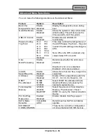
Page 49: ...led only values below 97C are valid Disabled Core Multi Processing Enable Disabled Determines whether the 2nd core is enabled Disabled 2nd core is disabled Enabled 2nd core is enabled Intel R SpeedSte...

Page 50: ...N Sub Menu Phoenix SecureCore tm Setup Utility Advanced SIO SMC227 CONFIGURATION Item Specific Help COM1 port 3F8 IRQ 4 COM1 mode RS232 COM2 port 2F8 IRQ 3 COM2 mode RS232 COM3 port 3E8 IRQ 10 COM3 mo...

Page 51: ...xternal Device TTL2 Internal Device RS422 External Device RS485 External Device COM3 port 3E8 IRQ 10 Disabled Configure COM3 using device options Disabled No configuration 3E8 IRQ 10 Set the base I O...

Page 52: ...sector Normal Password on boot Disabled AC97 Audio Interface Auto Cardbus 1394 Inferface Auto TPM Support Disabled RF Interface Control Item Specific Help Supervisor Password controls access to the s...

Page 53: ...r Enter HDD 1 Password Fixed disk boot sector Normal Write Protect Write protects the boot sector on the hard disk to protect against viruses Password on boot Enabled Disabled Enables password entry o...

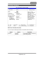
Page 54: ...Control F1 Help Select Item Change Values F9 Setup Defaults Esc Exit Menu Enter Select Sub Menu F10 Save and Exit RF Interface Control Sub Menu Selections You can make the following selections on the...

Page 55: ...ew or configure devices Up and Down arrows select a device and moves the device up or down f and r specifies the device fixed or removable x exclude or include the device to boot Shift 1 enables or di...

Page 56: ...nge Values F9 Setup Defaults Esc Exit Menu Enter Select Sub Menu F10 Save and Exit Exit Menu Selections You can make the following selections on the Exit Menu Feature Options Description Exit Saving C...

Page 57: ...VGA Windows 7 Ultimate 64 bit Run Setup exe in the directory of RF9 RK9 RT9 Drivers Win7 64bit VGA Win7Vista_64_151716 and then follow the instructions to install Windows XP SP3 Run winxp_14428 exe in...

Page 58: ...uch screen controller is in the optional COM4 it may be configured as touch screen and doesn t need BIOS setup b BIOS setting Set TTL1 for COM1 mode in Phoenix BIOS Setup Advanced SIO SMC227 CONFIGURA...

Page 59: ...ory of Utilities Windows 7 64 bit 9 Series Wireless Manager 20110222 and then follow the instructions to install Windows XP SP3 Run setup exe in the directory of Utilities Windows XP 32 bit 9 Series W...

Page 60: ...RF9 RK9 RT9 Drivers WinXP 32bit BLU_BC4_V5 x BlueSoleil 5 4 314 3 install and then follow the instructions to install GPS Optional Windows 7 Ultimate 64 bit First enter into the Wireless Manager to t...

Page 61: ...then select Browse my computer then select Browse for driver and search for RF9 RF9 RK9 RT9 Drivers Win7 64bit hc25_2_64bit_drivers then follow the prompt to complete installation Then copy the Conman...

Page 62: ...695 MB Chipset North Bridge Mobile Intel GM45 Express chipset Cantiga G MCH South Bridge Intel ICH9M Enhanced Display Standard LCD Type 15 LED Backlight Resolution 1024 x 768 XGA 1400x1050 SXGA Mode X...

Page 63: ...5 25 Removable Height 12 7mm Interface SATA I O Ports PS 2 x1 KB mouse USB 2 0 x 3 IEEE1394 Fire Wire x 1 LAN RJ45 x 1 Optional Modem Jack RJ11 x 1 PC Card Type I II x 1 Express Card PCI e x 1 Optiona...

Page 64: ...attery Primary Battery Type 9 x 18650 cells Lithium Ion Capacity 10 8V 8700mAh Dimension 103 mm W x 73 mm D x 38 mm H Weight 435 g 2nd Battery Optional Type 9 x 18650 cells Lithium Ion Capacity 10 8V...

Page 65: ...on pad Silicon Rubber TPE PCB FR 4 UL 94V0 Battery Rechargeable Lithium Ion 9 Cells per Pack Packing Carton Unbleached Paper Cushion Recyclable EPE Carrying bag Recyclable PE Fiber Quick Guide Recycle...

Page 66: ...ehicle Adapter Input Voltage 12 32V Input Current 9A max Output Voltage 19V Output Current 4A Wiring Cigarette lighter Truck battery Application Car or Truck installation 2nd Battery Trade off with OD...

Page 67: ...with v1 1 1 2 2 0 devices WWAN HSDPA UMTS 3 5G GPS GPS module supports both GPS and GALILEO systems KB Dust Cover KB Dust Cover is available for standard Keyboard PC Card Cover Besides the attached P...

Page 68: ...Primary and Secondary Batteries respectively It accepts power from AC adapter or vehicle adapter and charged batteries It takes approximately 6 hours to fully charge both batteries COM 3 4 Card and A...

Page 69: ...strengthen the security With TPM users are able to encrypt the folders and files directly and make the important file be more secure and be with an additional protection In other words your TPM encryp...

Page 70: ...recommended for cleaning water and dust For salty water please clean with fresh water then blow dry with an air gun Be sure not to turn the computer upside down while there is water being applied Trou...

Page 71: ...heet with the following information Note Please keep a copy of this sheet for your records Name Address Unit serial number Place and date of purchase or the original invoice number Date of failure A D...

Reviews: