background image

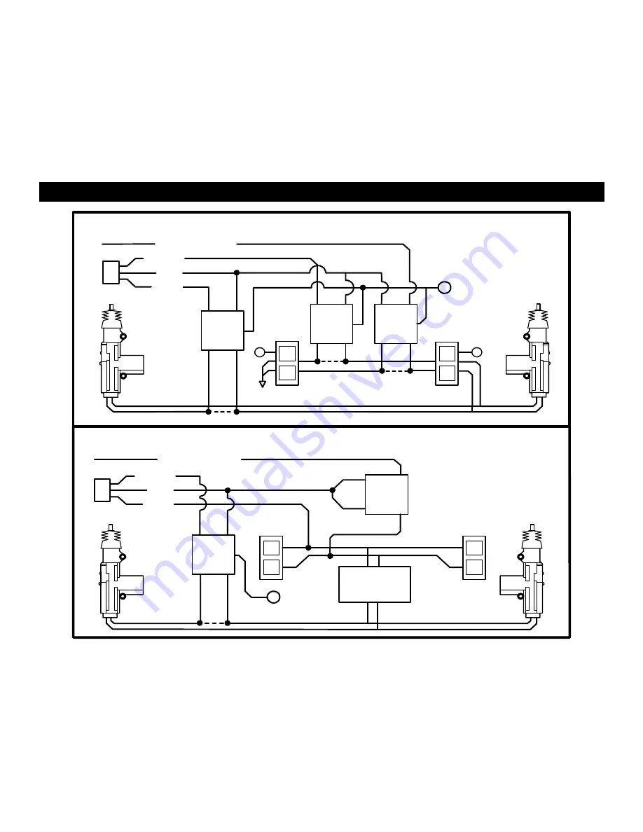
SEPARATE DRIVER’S DOOR UNLOCK WIRING 


WIRING FOR REVERSE POLARITY DOOR LOCKS

WHITE/BLUE

GREEN

FUSED

RED

+12V

BLUE

+

DRIVER'S

86

85

86

85

DOOR MOTOR

86

85

87

87

87

30

87A

30

87A

30 87A

+

+

L

L

CUT

UL

UL

CUT

CUT

UNLOCK WIRE

WIRING FOR POSITIVE TRIGGER DOOR LOCKS

WHITE/BLUE

GREEN

86

85

RED

BLUE

87

30

DRIVER'S

DOOR MOTOR

86

85

L

L

87

UL

UL

87A

30

FACTORY LOCK

RELAYS

+12V

+

FUSED

UNLOCK WIRE

CUT


Summary of Contents for CS-2007

Page 1: ...n by the installing dealer i e Door Locks Flashing Lights Starter Disable Hood Trunk and Auxiliary Remote Outputs etc TECH SUPPORT Mon Fri 8 00 AM 4 30 PM Pacific Time 800 998 6880 website www crimestopper com email tech support crimestopper com This device complies with FCC Rules part 15 Operation is subject to the following two conditions 1 This device may not cause interference and 2 this devic...

Page 2: ...h pedals or the steering column The alarm control module should be mounted in a concealed location The Placement of the module will affect the distance from which the remote transmitter can control the unit The antenna wire should be routed away from any metal if possible Do not alter the length of the antenna wire or route it with other wires Do not ground the antenna wire Underdash Mounting If y...

Page 3: ...vehicles require separate right and left circuits Use a dual relay or 2 diodes to separate the output signal RED WIRE 12V POWER INPUT 15 amp fuse Connect to 12 Volt source with supplied fuse holder Recommended location for this connection is at the vehicle battery positive terminal BROWN WIRE SIREN OUTPUT 2 Amp Max Connect to RED siren wire BLACK WIRE SYSTEM CHASSIS GROUND THIS WIRE MUST BE CONNEC...

Page 4: ...the key in both On and Start positions 4 PIN PLUG OPTIONAL FEATURES ACCESSORY WIRING WHITE WIRE PARKING LIGHT OUTPUT 2 Optional European Vehicles This wire is used on European vehicles that require left and right isolated parking light output circuits Connect this wire to the 2nd half of the circuit from where the other WHITE wire Main Harness is located WHITE ORANGE WIRE REMOTE OUTPUT 2 or MOBILE...

Page 5: ...LUG YELLOW DOOR LOCKS OPTIONAL GREEN Negative LOCK pulse Positive UNLOCK pulse RED 12V Coil Power for external relays Term 86 BLUE Negative UNLOCK pulse Positive LOCK pulse WHITE BLUE WIRE PASSENGER S DOOR UNLOCK OUTPUT Optional requires relay Connects to unlock circuit for passenger door s when using separate driver s door unlock option See DOOR LOCK WIRING for configuration options DETERMINING D...

Page 6: ...LOCKING UL UL RELAYS RELAYS UNLOCK UNLOCK IN4001 DIODES IN4001 AFTERMARKET MOTOR DOOR LOCK WIRING REVERSE POLARITY DOOR LOCK WIRING GREEN GREEN FUSED FUSED RED RED 12V 12V BLUE BLUE 86 85 86 85 86 85 86 85 87 87 87 87 30 87A 30 87A 30 87A 30 87A L CUT UL CUT MASTER SWITCH Diodes are recommended for protection of the door lock outputs on Positive Negative systems Not included ...

Page 7: ...EN FUSED RED 12V BLUE DRIVER S 86 85 86 85 DOOR MOTOR 86 85 87 87 87 30 87A 30 87A 30 87A L L CUT UL UL CUT CUT UNLOCK WIRE WIRING FOR POSITIVE TRIGGER DOOR LOCKS WHITE BLUE GREEN 86 85 RED BLUE 87 30 DRIVER S DOOR MOTOR 86 85 L L 87 UL UL 87A 30 FACTORY LOCK RELAYS 12V FUSED UNLOCK WIRE CUT ...

Page 8: ...ble Unlock Pulse ON OFF INDICATES THE FACTORY PRESET SETTING SEE OPTION DESCRIPTIONS BELOW 1 PASSIVE ARMING This option controls the Passive Automatic Arming feature If ON arming will occur 30 Seconds after the ignition is turned off and the last door has been closed The LED will begin flashing rapidly while counting down If a door is reopened the system will wait LED solid for the door or zone to...

Page 9: ...ing trunk or other AUX feature Factory Default setting is ON 8 REMOTE OUTPUT 2 or M A P SWITCH This feature controls the alarm system s uses a second remote output or an output for Mobile Accessories Protection controlled by Valet Park Mode Factory setting is Remote Output 2 9 DOOR ZONE OPEN WARNING DELAY This setting changes the delay time in which the alarm system begins to monitor the Door Hood...

Page 10: ... both VEH 2 remotes to VEH 1 See Transmitter Code Programming 3 Make sure all remotes operate VEH 1 4 Insert Jumper onto J10 pins 5 Retest the remote controls VEH 1 Remotes should operate this system with button 1 VEH 2 Remotes should now operate this system with buttons 1 2 If this does not operate as described above re check solder pads verify they are connected PROGRAMMING VEHICLE 2 1 Make sure...

Page 11: ...override program button again and hold until the siren chirps twice Instead of turning Off Ignition 3 Turn Off Ignition after the 2 chirps are heard 4 The System should now have a 3 second lock and unlock pulse Repeat this procedure to revert back to 0 75 Sec Note You may Choose to perform this change when adding a new transmitter to the system or just reprogram re learn one of the existing remote...

Page 12: ...ER LOCATION A 1 R 1 R 2 J9 J10 JUMPER PLUG SIDE VIEW JUMPER PINS J10 2 VEHICLE J9 CARJACK C2 A1 R 1 R 2 J9 J10 TOP OF CONTROL MODULE STARTER DISABLE CUT START WIRE STARTER BROWN WHITE IGN SWITCH BROWN WHITE ...

Page 13: ...D DEPENDING ON THE TYPE OF DOME LIGHT CIRCUIT DOME LIGHT ILLUMINATION WITH ACTIVE RE ARM 12V BAT 86 85 30 87A DOOR PIN DOME LIGHT WHITE GREEN DOME ILLUMINATION CONNECTS TO EITHER 12V or GROUND DEPENDING ON THE TYPE OF DOME LIGHT CIRCUIT DRIVER S SWITCH PASSENGER DOOR SWITCHES 87 CUT WIRING FOR DOOR TRIGGER GREEN or VIOLET DOOR TRIGGER WIRE ...

Page 14: ...RN TRIGGER OPTIONAL M A P WIRING 86 85 ACC 87 SWITCHED 30 87A START IGN ACC CUT OFF F M 105 5 wire of mobile accessories such as Audio system Connect relay as shown to interrupt the power RADIO WHITE ORANGE M A P OUTPUT MOBILE ACCESSORY PROTECTION or Cellular telephone The Alarm will disconnect these accessories when in VALET PARK MODE ...

Page 15: ...one after 2 cycles Alarm is still armed with door zone bypassed 7 Disarm system with transmitter chirps should sound indicating prior intrusion TESTING PROCEDURES Sensors 1 Arm system with transmitter 2 Wait 10 30 seconds for sensors to settle and become active Dash LED should be flashing rapidly A Dual Stage Shock Sensor Tap or Slap on a window or bumper with light to medium force This should tri...

Reviews: