background image


21 


3


O

PERATING

-I

NTRODUCTION


3.1


O

PERATING PRINCIPLE


• The RCE isolator is an electronic distributor designed with MOSFET technology limiting voltage drops, to distribute the 

charging current to several batteries, or battery banks, with the same nominal voltage. 

• The RCE 

isolator prevents current from flowing from one battery to another. It thefore allows the isolation of the 

battery banks. 

• The RCE isolator charges the batteries with regulated DC energy sources and isolates your electrical circuits, it acts as 

if there were two or three separated outputs. 

•There is no priority output, it is the current used by the 

more energy-intensive device that will generate the priority. 

• Any unused output should be left disconnected.


The RCE isolator is not a voltage regulator, it must always be placed downstream of a regulated source: 

-


Battery charger 

-


Wind turbine regulator 

-


Alternator 

-


MPPT 

-


Etc. 


3.2


O

VERVIEW PRESENTATION


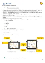
RCE isolators can be divided in 3 groups depending on : 
 

 The number of Inputs and Outputs 

• 

The maximum Current 

 The presence of IG terminal (Ignition terminal) 


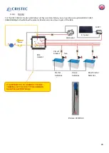
RCE/100-1E-2IG model  


       RCE/100-2E-3 Model 


The Led 

indicates if the RCE has a power source connected 


1 Input 


2 Inputs 


IG  

terminal 

Outputs B+ 

Outputs 

B+ 

Outputs B- 

Summary of Contents for RCE/100-1E-2IG

Page 1: ...anual del usuario de aisladores de bater as RCE RCE 100 1E 2IG RCE 100 1E 3IG RCE 100 2E 3 RCE 150 1E 2IG RCE 150 1E 3IG RCE 180 1E 2IG RCE 180 1E 3IG RCE 200 1E 3IG S A S CRISTEC 31 rue Marcel Paul Z...

Page 2: ...1 Manuel d utilisation en Fran ais 2 User Manual in English 16 Manual de instrucciones en Castellano 29...

Page 3: ...TEUR 9 4 3 CABLAGE 10 4 3 1 CABLES DE LIAISON 10 4 3 2 COSSES ELECTRIQUES 10 4 3 3 CIRCUIT DE PROTECTION ELECTRIQUE 10 4 4 TYPES DE SCHEMAS ELECTRIQUES 10 4 4 1 TERMINOLOGIE ET SYMBOLES 11 4 4 2 CIRCU...

Page 4: ...TIONS RELATIVES A LA SECURITE Mat riel de classe I selon la norme NF EN 60335 2 29 Les prescriptions d installation sont contenues dans la norme NFC 15 100 L installation doit tre r alis e par un lect...

Page 5: ...urit leur ont t donn es et si les risques encourus ont t appr hend s alors ils ou elles pourront l utiliser sous la surveillance d une personne responsable Les enfants ne doivent pas jouer avec l appa...

Page 6: ...s vis vis des chauffements de l appareil L quipement est con u pour tre mont sur une paroi verticale selon les indications fournies dans ce manuel Il est imp ratif de conserver une zone de 100mm autou...

Page 7: ...sitionn dans un endroit sec et bien ventil Dispositions vis vis des mat riels inflammables Le r partiteur de charge ne doit pas tre utilis proximit de mat riels liquides ou gaz inflammables Les batter...

Page 8: ...ais de d montage remontage et tests ainsi que tous les autres frais non cit s Notre garantie ne peut en aucun cas donner lieu une indemnit CRISTEC ne peut tre tenue pour responsable des dommages dus l...

Page 9: ...sorties distinctes Il n y a pas de sortie prioritaire c est l appel de courant utilis par le plus gros consommateur qui va g n rer la priorit Toute sortie non utilis e doit tre laiss e telle qu elle L...

Page 10: ...e d gagement de l ordre de 100mm autour du r partiteur est recommand e pour ventilation Ne rien d poser sur le r partiteur Ne pas placer le r partiteur directement sur le moteur Il est pr f rable d in...

Page 11: ...ans le tableau ci dessous Tableau des sections minimales de c bles R f rences Section des c bles Entr e Sortie Section du c ble IG et BAT RCE 100 25 mm 1 mm RCE 150 35 mm RCE 180 50 mm RCE 200 4 3 2 C...

Page 12: ...cessitant pas de r f rence le montage est tr s simple Une r f rence lectrique sur la borne BAT du RCE vers la masse de la batterie la section peut tre 1mm un c ble de la bonne section voir tableau des...

Page 13: ...e la tension batterie venant de la cl de contact Si la source est solaire ou olienne ou autre la borne IG doit tre connect e au p le positif d une batterie via un interrupteur Vers les consommateurs a...

Page 14: ...ur une ou deux entr es du RCE Photo du kit r partiteur 1 2 IL EST IMPERATIF DE CONNECTER LA BORNE BAT DU REPARTITEUR AU NEGATIF COMMUN DU PARC BATTERIE Tout manquement d t riorera les composants du r...

Page 15: ...oussi reuse les nettoyer p riodiquement par aspiration les d p ts de poussi re pouvant alt rer l vacuation de la chaleur V rifier l tat de charge des batteries tous les 3 mois Une v rification annuell...

Page 16: ...parti sur 2 sorties Nous consulter en cas de courant de charge constant RCE 3 SORTIES Pour le courant maximum total r parti sur 3 sorties Nous consulter en cas de courant de charge constant Code Artic...

Page 17: ...2 FIXING THE ISOLATOR 22 4 3 WIRING 23 4 3 1 BATTERY CABLES 23 4 3 2 ELECTRICAL LUGS 23 4 3 3 ELECTRICAL PROTECTION CIRCUIT 23 4 4 TYPES OF ELECTRICAL DIAGRAMS 23 4 4 1 TERMINOLOGY AND SYMBOLS 24 4 4...

Page 18: ...in the NFC 15 100 standards The installation must be carried out by an electrician or a professional installer It is essential not to install repair start any maintenance or cleaning on this device w...

Page 19: ...f the appliance This appliance is designed to be mounted on a vertical wall as indicated herein It is imperative have a gap of 100mm around the isolator The installer must ensure that the temperature...

Page 20: ...rding inflammable materials The isolator should not be used near inflammable materials liquids or gases The batteries can emit explosive gases please follow the manufacturer s instructions carefully w...

Page 21: ...ckaging disassembly reassembly and testing and all other costs not mentioned Our warranty can t give rise to an indemnity CRISTEC cannot be held responsible for any damage caused by the use of the bat...

Page 22: ...f there were two or three separated outputs There is no priority output it is the current used by the more energy intensive device that will generate the priority Any unused output should be left disc...

Page 23: ...ce zone of around 100mm around the splitter is recommended for ventilation Do no put anything against or on the top of RCE Do not install the isolator on the engine It is preferable to install the RCE...

Page 24: ...ctions They must be fitted with an insulating sleeve to avoid the risk of electric shock 4 3 3 ELECTRICAL PROTECTION CIRCUIT The electrical protections fuses must be placed upstream of the splitter Th...

Page 25: ...the RCE and the negative terminal of the battery the cross section should be 1mm A cable of the correct cross section see table of cable cross sections between the terminal of the RCE and the regulat...

Page 26: ...ing from the ignition key If the voltage source is solar or wind or other the IG terminal must be connected to the positive pole of a battery through a switch Starter batteries House batteries Bow thr...

Page 27: ...n on one or two inputs of the RCE Picture of RCE kit 1 2 IT IS IMPERATIVE TO CONNECT THE BAT TERMINAL OF THE RCE TO THE COMMON NEGATIVE BATTERY BANK Tout manquement d t riorera les composants du r par...

Page 28: ...sphere vacuum clean them regularly since dust deposits may adversely affect heat dissipation Check the state of battery charge every 3 months Nuts and screws should be tightened annually to ensure eff...

Page 29: ...urrent balanced between the 2 outputs consult us for a pemanent current RCE 3 OUTPUTS Maximum current balanced between the 2 outputs consult us for a permanent current Part Number RCE 100 1E 3IG RCE 1...

Page 30: ...APRIETE DEL AISLADOR 36 4 3 CABLEADO 36 4 3 1 CABLES DE BATER A 37 4 3 2 TERMINALES DE CABLES 37 4 3 3 CIRCUITO DE PROTECCI N EL CTRICA 37 4 4 DIAGRAMAS EL CTRICOS 37 4 4 1 TERMINOLOG A Y S MBOLOS 38...

Page 31: ...AD Material de clase I seg n la norma NF EN 60335 2 29 Las prescripciones de instalaci n est n indicadas en la norma NFC 15 100 La instalaci n debe ser realizada por un electricista o un instalador pr...

Page 32: ...31 entonces podr n utilizar el dispositivo bajo control de una persona responsable Los ni os no deben jugar con el dispositivo...

Page 33: ...s calentamientos del aparato El equipo ha sido dise ado para ser montado en una pared vertical seg n las indicaciones que figuran en este manual Es absolutamente necesario mantener una zona despejada...

Page 34: ...eco y bien ventilado Disposiciones respecto a los materiales inflamables El aislador no debe utilizarse cerca de materiales l quidos o gases inflamables Las bater as pueden emitir gases explosivos par...

Page 35: ...costos de desmontaje montaje y pruebas o cualesquiera otros costos no citados Nuestra garant a no puede en ning n caso dar lugar a una indemnizaci n CRISTEC no puede considerarse responsable de los da...

Page 36: ...l ctricos act a como si fueran dos o tres salidas separadas No hay salida prioritaria es la corriente utilizada por el dispositivo que consume m s energ a la que generar la prioridad Cualquier salida...

Page 37: ...00 mm alrededor del aislador para ventilaci n No ponga nada en contra o sobre el RCE No instale el aislador sobre el motor 4 2 FIJACI N Y APRIETE DEL AISLADOR El aislador debe fijarse correctamente co...

Page 38: ...3 2 TERMINALES DE CABLES Los terminales de cables deben engarzarse con unos alicates adecuados para resistir las vibraciones mec nicas y evitar el sobrecalentamiento La dimensi n debe seleccionarse en...

Page 39: ...le el ctrico entre el terminal BAT del RCE y el terminal negativo de la bater a la secci n debe ser de 1 mm Un cable de la secci n correcta ver tabla de secciones de cables entre el terminal del RCE y...

Page 40: ...e contacto Si la fuente de voltaje es solar e lica u otra la terminal IG debe conectarse al polo positivo de una bater a a trav s de un interruptor ES IMPERATIVO CONECTAR EL TERMINAL DE BATER A DEL RC...

Page 41: ...na o dos entradas del RCE Foto del kit RCE 1 2 ES IMPERATIVO CONECTAR EL TERMINAL DE BATER A DEL RCE AL BANCO DE BATER A NEGATIVO COM N Tout manquement d t riorera les composants du r partiteur et pro...

Page 42: ...n ambiente polvoriento hay que limpiarlos peri dicamente por aspiraci n ya que la acumulaci n de polvo puede alterar la evacuaci n del calor Es necesario realizar una verificaci n anual del apriete de...

Page 43: ...xima sumida en las 2 salidas Cons ltenos para corrientes permanentes RCE 3 salidas Corriente m xima sumida en las 2 salidas Cons ltenos para corrientes permanentes C digo art culo RCE 100 1E 3IG RCE...

Reviews: