23
4.3
W
IRING
To connect and disconnect a cable, all power sources must be switched off and the batteries isolated.
4.3.1
B
ATTERY CABLES
It is essential to check the compatibility of voltage, current and the configuration according to the type of batteries
connected before any power-up.
For battery cables up to
3 metres
, the cross-section of the battery cables should be at least equal to or greater than the
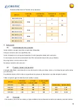
values provided in the table below:
Table of minimum cable cross-sections
Item
Inpout and Output cross sections
IG and BAT
–
cable cross section
RCE/100
25 mm²
1 mm²
RCE/150
35 mm²
RCE/180
50 mm²
RCE/200
4.3.2
E
LECTRICAL LUGS
The cable lugs must be crimped with suitable pliers to resist to mechanical vibrations and to avoid overheating.
The dimension must be selected according to the cross sections of the cables and the threaded rods (see table of cable
sections).
They must be fitted with an insulating sleeve to avoid the risk of electric shock.
4.3.3
E
LECTRICAL PROTECTION CIRCUIT
The electrical protections (fuses) must be placed upstream of the splitter.
They must be sized with the same ratings as your isolator (eg for an RCE/100 -> 100A).
Any non-compliance with these recommendations will result in the systematic cancellation of the guarantee.
4.4
T
YPES OF ELECTRICAL DIAGRAMS
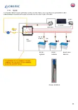
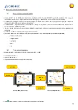
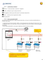
It is advisable, according to your electrical installation, to choose the good options.
This chapter deals with simple assemblies, regulated sources requiring an excitation voltage and also the isolator with
two inputs requiring an excitation voltage.
Checking of the polarity
Before connecting the batteries to the isolator, it is imperative to check their polarity. Also check the battery
voltage using a calibrated voltmeter. A low value of voltage on certain types of batteries may reflect an
irreversible degradation of them and therefore an impossibility of recharging. Any damage due to a connection
fault will be excluded from the warranty.


