2
WWW.CRISTEC.FR
Installation
The
voltage
guard
has
to
be
installed
on
a
solid
surface
and
in
a
dry
and
well
ventilated
place.
Never
use
the
voltage
guard
where
there
is
any
danger
of
explosive
gas.
Connection
and
possible
additional
protections
shall
be
made
in
compliance
with
local
and
concerned
application
regulations.
Appropriate
terminal
shall
be
used
to
avoid
bad
connection.
Fasten
the
bolts
tightly
but
not
over
tighten
them.
Use
wiring
with
the
appropriate
diameter.
Make
sure
the
battery
is
fused
with
the
right
value.
This
fuse
can
be
70A
maximum,
limited
by
the
voltage
guard.
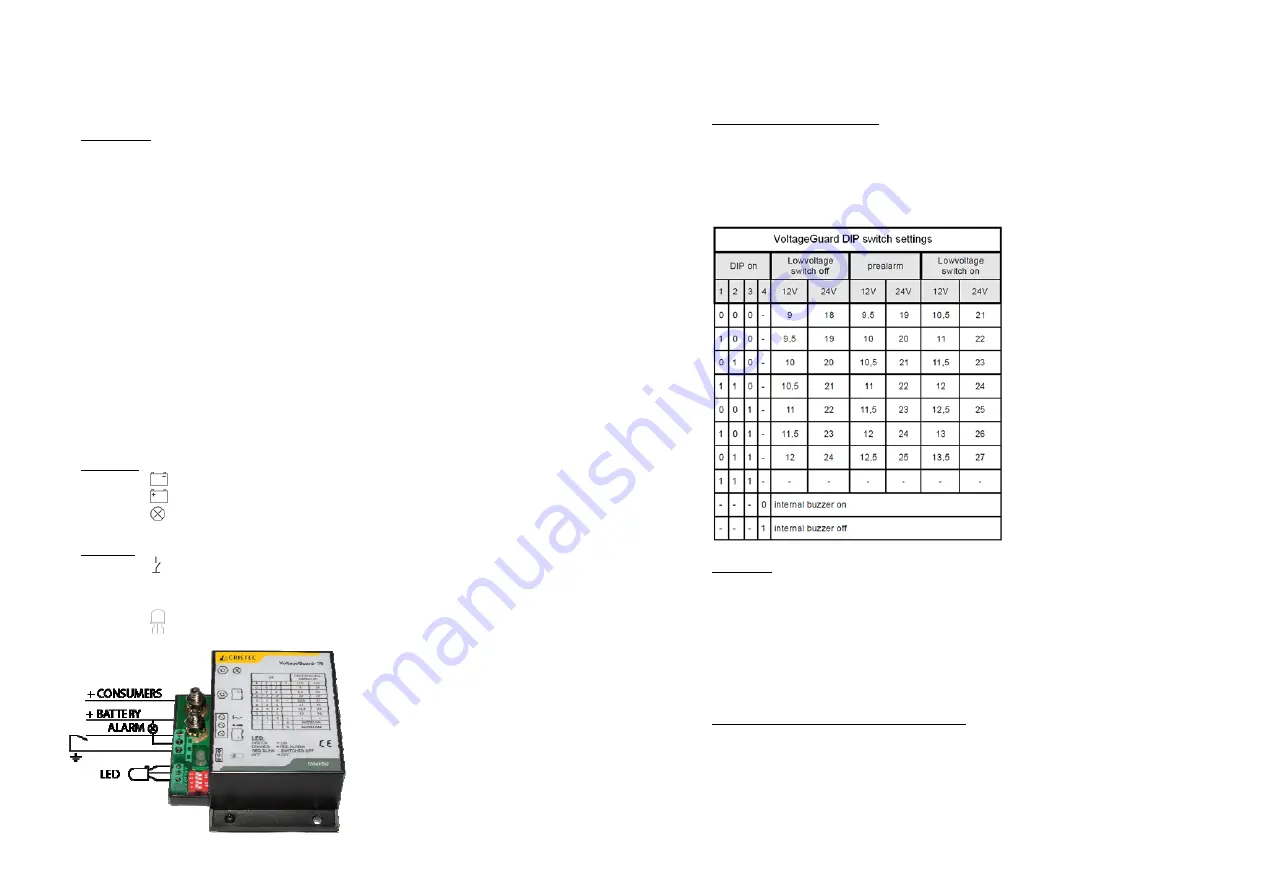
Connect
the
voltage
guard
according
the
wiring
diagram
as
shown
below.
Standard
:
Connect
the
terminal
to
the
ground
of
the
installation.
Connect
the
terminal
to
the
positive
pole
of
the
battery.
Connect
the
terminal
to
the
consumers
+
terminal.
Optional
:
Connect
the
terminal
to
a
switch
to
ground
to
use
main
switch
function.
Connect
the
!
terminal
to
an
external
alarm.
This
signal
switches
to
ground
in
case
of
a
low
battery
(maximum
alarm
load
1A).
Connect
the
terminals
to
an
external
three
colour
LED
if
desired
.
3
WWW.CRISTEC.FR
Low
voltage
cut
‐
off
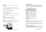
setting
The
low
voltage
setting
can
be
adjusted
by
the
dip
switches
according
to
the
table
below.
The
voltage
guard
is
permanently
switched
on
when
DIP
switches
1,
2
and
3
are
on.
In
this
case
the
low
voltage
protection
is
disabled.
The
voltage
guard
works
only
between
8VDC
and
31VDC.
Use
DIP
switch
4
to
enable
or
disable
the
internal
buzzer.
Power
up
When
the
power
is
supplied
to
the
voltage
guard
an
internal
self
‐
test
is
done.
At
this
moment
the
voltage
guard
determines
the
nominal
system
voltage.
In
this
situation
the
status
LED
will
flash
once
red
‐
green
and
a
beep
can
be
heard.
At
a
power
up
voltage
below
16V,
the
voltage
guard
sets
itself
to
12V
system
voltage.
If
the
power
up
voltage
is
higher
than
16V,
the
voltage
guard
sets
itself
to
24V
system
voltage.
Using
the
voltage
guard
as
a
main
switch
If
a
panel
switch
is
connected
according
to
the
drawing,
the
main
switch
function
can
be
used.
The
output
is
turned
off
when
the
switch
is
closed.
The
status
LED
is
off
and
flashes
four
times
a
minute.
The
normal
voltage
guard
function
is
activated
when
the