background image

Summary of Contents for 32K Bytesaver

Page 1: ...Cromemeo 31K Bytesaver Five Dollars ...

Page 2: ... Cromemco CopyrIght c 1978 by Cromemco Inc A1ll1ghlS reserved 3cromemco irocorpo t d Tomorrow s Computers Today l OBER AAOO E UOUN1 A N V E W c joIljolJ Part No 023 0002 April 1979 ...

Page 3: ...elect BANK 0 On RESET Or POWER ONCLEAR 16 2 7 Direct Memory Access _ 16 Section 3 PROM Programming Instructions 19 3 1 Programming From RODS Or 2 80 Monitor 19 3 2 Programming From 3K Control BASIC 20 3 3 Programming From l 80 Assembly Code 22 Section 4 Theory Of Operation 24 4 1 Power Supplies 24 4 2 Addressing 24 4 3 Memory Read Cycles 25 4 4 Memory Write Cycles 25 4 5 DMA Cycles 25 Section 5 As...

Page 4: ...re 5 32K BYTESAVER Addressing __ __ 7 Figure 6 Two 32K BYTESAVEAS Spanning The 64K Address Space _ 9 Figure 7 Example 4 Switch Settings And Memory Map 11 Figure 8 The Memory Map With Multiple Memory Banks 12 Figure 9 Example 5 Switch Settings 13 Figure 10 Example 5 Memory Map 14 Figure 1 DMA OVERRIDE Example Configuration 17 Figure 12 Control BASIC Memory Map _ 21 Figure 13 IC Pin Position 28 ...

Page 5: ......

Page 6: ...r wires This manual consists of four basic sections Operating Instructions PROM Programming Instruc tions Theory of Operation and Assembly Instruc tions If you purchased a 32K BYTESAVEA kit the Assembly Instructions provide step by step con struction and initial test procedures The section Switch Options An Overview of the Operating Instructions provides a 32K BYTESAVER opera tional overview for t...

Page 7: ......

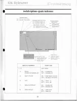
Page 8: ...o program a PROM you will additionally need to run software described in the Section 3 PROM PROGRAMMING INSTRUCTIONS 2 1 Switch Options An Overview The 32K BYTESAVER is configured by setting six switch groups located along the top edge of the board see Figure 1 To provide an operational overview and for later quick reference the function of each switch group is briefly explained in this section Fi...

Page 9: ...it state per machine cycle the OFF position introduces no wait states When used in a Cromemco system with a ZPU run ning at 4 MHz position the switch ON The switch may be left OFF when operating at 2 MHz The A 15 switch memory maps the 32K BYTE SAVER board in the lower 32K half of the memory address space lOOOOH 7FFFHI when in the OFF pOSItion IA15 0 and memory maps the board in the upper 32K half...

Page 10: ... disable socket programming associate the board socket numbers IROM0 ROM15 with the numerals printed above the two switch DIPs on the p c board 15 to the far left ato the far right 4 BANK SELECT Switches The eight BANK SE LECT switches map the 32K BYTESAVER IOta any combination of eight possi ble 64K byte memory banks bank 0 bank 71 Set ting a BANK SELECT switch ON logically places the board in th...

Page 11: ...he switch set lings would be as shown in Figure 3 To program a PROM in socket ROMe all switch settings remain the same except the PROGRAM POWER switch which IIl st be turned ON 0 Figure 3 Example 1Switch Settings PROGRAM POjER BANI DISABLE r A1S 1 DON r CARE SINCE OMA OVERRIDE DISABLED iDISABLE ROM a ROM 15 l PROGRAMMING fi l L r t l 1 U t 1 L ALL SOCKET PAIRS IN MEMORY MAP l OMA OVERRIDE DISABLED...

Page 12: ...f memory solely for DMA transfers assume this card is assigned to memory bank 1J You decide to assign the 32K BYTESAVER 10 memory bank 0 so it will be enabled on iJ system Power Qn Clear or RESET see Section 2 6 for details The appropriate 32K BYTESAVER switch settings for memory read operations are then shown in Figure 4 0 Figure 4 Example 2Switch Settings PROGRAM POWER r BANKS ENABLED I Ar5 O DM...

Page 13: ... board Board chip and byte on chip are all decoded t from the sixteen bit address seni out by the CPU on the S l00 bus Since the board capacity is 32K bytes board select is generated by the high order address line A15 There are sixteen ROM sockets so the next four high order address lines A11 A14 are used to hardware generate chip enable selecting ROM0 ROM 151 and the remaining eleven address line...

Page 14: ... memory Address lines A 11 A 14 feed two one of eight decoders ICG and le7 in the 32K BYTESAVER Schematic to generate select signals to each ROM socket The entire 64K address space may then be spanned by two 32K BYTESAVER 8 boards Figure 6 illustrates such an arrangement along with the address range spanned by each ROM socket Example 3 Suppose you programmed two 2716 PROMs with Cromemco s Z 80 MON...

Page 15: ...O ROM 9 C800 A 32K ROM 8 COOO BY ESAVER WITH AIS I ROM 1 8800 ROM 6 8000 ROM 800 ROM 000 ROM 3 9600 ROM 2 9000 ROM I e600 ROM D 8000 64K BYTES ROM 15 1800 ROM 14 1000 ROM 13 6800 ROM 12 6000 ROM II 5600 ROM 10 5000 ROM 9 4600 A 321 ROM 8 BYTESAVER 4000 WITH AIS O ROM 7 3800 ROM 6 000 ROM 5 2800 ROM 4 2000 ROM 1800 ROM 2 1000 ROM I 0800 ROM 0 0000 9 ...

Page 16: ...g OOOOH 7FFFH and a 32K BYTESA VER assigned to 10 BOODH FFFFH The Cromemco Floppy Disc COIl troller board is factory shipped with the RODS monitor program in ROM memory on the 4FDC board The RODS program spans addresses COOOH C3FFH so yO J SHADOW sockets ROMS and ROM9 leavmg a hole at COOOH C7FFH whIch RODS then partially fills Further aswme you program one half of a 2716 with Cromemco s Z 80 Moni...

Page 17: ...le 4Switch Settings And Memory Banks I l to C L r OIO TOIl n S AR I I r 1 1 C3 Cr uK BYT SAJ R r 1 A f f I OIPTf _ IlIPI fl r 0 f LH J U DUI Ll l lVH F Xl WJoTl _oo Ill l m S T I L fl I 1 _ tor I y t f I 011 1 _ 0 _T 0 t 8 H W 1 11 ...

Page 18: ...o enable memory banks switch select BANK ENABLE in the ADDR CONTROL switch group When this IS done the 32K BYTESAVER is logical ly placed In one or more 64K byte memory banks with the eight BANK SELECT switches and bank addressing IS software controlled by executing the OUT 40H A or equivalent Z 80 instruction Memory may be stacked up to eight banks deep see Figure 81 Positioning one or more BANK ...

Page 19: ...he banks activated by the control byte Iogi calOR the board responds when addressed and thus is placed in the memory map When this condition occurs the green LED indicator lights Conversely if the 32K BYTESAVER is switch mapped into no bank activated by the output con trol byte the board will not respond when address ed and thus is out of the memory map_ When a control byte inactivates the board t...

Page 20: ...boards are switch assigned to the same mem ory bank or b Two or more 16 bit address overlapping memory boards assigned to disjoint memory banks are simultaneously activated by the samt control byte Example 5 Suppose two 32K BYTESAVERs are both mapped mto the upper 32K of memory fA 75 1 and theIr memory bank switches are set as shown in Figure 9 The rewlting memory map is then shown In Figure 10 Fi...

Page 21: ...2 0004 3EB1 0340 LD OUT A 10000001B 40H A LOAD 1000 0001 INTO REG A iOUTPUT CONTROL BYTE TO PORT 40H iNEXT INSTRUCTION Executing the instructions below places board A in an active memory bank and board B in an inactive memory bank board A available for memory read PROM programming and OMA transfers board B inaccessible ADDR OBJECT MNEMONIC COMMENT 0000 0002 0004 3E01 0340 LD OUT A 00000001B 4I3H 1...

Page 22: ...er data at a rate limited only by the memory access time The general features of a DMA transfer are then Fast asynchronous read or write access to memory The DMA device should not be responsible for many overhead tasks such as memory bank switching to keep the memory access as quick as possible The access is direct no CPU intervention to slow the transfer The DMA device must be capable of control ...

Page 23: ...oard in effect does not differen tiate between a DMA data transfer and a normal read write cycle in any way The 32K BYTESAVER does differentiate be tween DMA and non DMA transfers with OMA OVERRIDE ENABLED as shown in the last two table entries A typical application demonstrating how DMA OVERRIDE works is shown in Figure 11 Figure ll DMA OVERRIDE Example Configuration RESPONDS TO AoDRiCONTROL DMA ...

Page 24: ...e pH LOA line high board A automatically disables and board B enables when the 5 100 bus address is in the range 8000H _ I I I I 18 FFFFH regardless of which board was in an active memory bank before the request Thus the DMA OVERRIDE feature is seen as a means of overriding logical memory bank boundar ies during a DMA transfer This provides a fast way of vectoring the DMA device to the DMA board t...

Page 25: ... ...

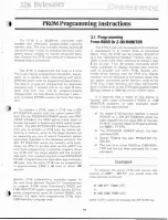
Page 26: ...mmed in approximately 2 04B x 50 msec or about 100 seconds Specific 2716 programming examples appear in the next three sections Section 3 1 illustrates how to program 2716s using Cromemco s RDOS and Z B0 MONITOR system commands Section 3 2 dis cusses programming using 3K Control BASIC and Section 3 3 deals with programming 27165 from Z 80 Assembly Language code 19 3 1 Programming From RODS Dr l BO...

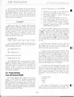
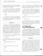
Page 27: ... the PRO GRAM POWER switch OFF_ 3K Control BASIC logically partitions memory into pages where 1 page 256 bytes Pages 0 and 1 IOOOOH 01 FFH are not used by CB pages 2 and 3 I0200H 03FFH are used for variables the input buffer and the stack pages 4 thru 31 10400H 1FFFH are normally used for CB program text and arrays and pages 32 on 12000H end of user RAM are normally used to save CB program files l...

Page 28: ... 32K Bytesaver Figure 12 Control BASIC Memory Map ADDRESS FFFFH COOOH 8000H 400QH I CB FILES PAGES 32 255120H FFHI CB PROGRAM TEXT AND ARRAYS 2aaOH OOOQH 10 H IFHI C l I 0 3 OQH 03H 21 ...

Page 29: ...try again Turn OFF the PROGRAM POWER switch after programming Assume now you move the two PROMs to 32K BYTESAVER sockers ROMO and ROMI fBODDH 8FFFH or pages 128 143 for running Sockets ROMO and ROMI should be PROGRAM 0 5 ABLED to prevent inadvertent re programming To run the program issue the command RUN 128 Or to bring the program into the text area for edit ing type LDAO 128 0 3K Control BASIC a...

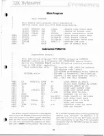
Page 30: ...does not verify BC DE and HL changed 0000 CS PGM2716 PUSH BC iSAVE SWATH ON STACK 000E EDB0 LDIR BLOCK MOVE SOURCE TO EPROM 0010 Cl POP BC RESTORE SWATH TO BC 0011 2B DEC HL iADDR LAST SOURCE BYTE 0012 IB VERIFY DEC DE ADDR LAST EPROM BYTE 0013 1A LD A DE iEPROM BYTE TO ACC 0014 EDA9 CPO COMPARE A TO HL 0016 E21E00 JP PO EXIT iTHRU VERIFY IF BC 00H 0019 2BF7 JR Z VERIFY iNOT THRU NEXT BYTE 001B 3E...

Page 31: ... ...

Page 32: ...ignals from IC6 and IC7 are logically ANDed by pairs IIC5 and IC8L and the SHADOW ROM switches parallel connect all of these ANDed outputs to node BOARD ENABLE If either of the socket pair is chip selected with a low level from IC6 or IC7 the AND output will go low and if the corresponding SHADOW ROM switch is closed lON BOARD ENABLE will go low thus disabling the board If 26 volts is not present ...

Page 33: ...ain goes high After the pRDY line is sampled high program execution resumes The coincidence of MEM WRITE and BOARD ENABLE clears PROGRAM PULSE counters IC28 and IC29 These dual 4 bit counters are then driven by the 2 MHz CLOCK line and they along with one of ten decoder IC30 and D type flip flop lC31 generate a digitally counted 50 msec PROGRAM PULSE which feeds the 2716 PROG input during programm...

Page 34: ...setting is irrelevant When DMA OVERRIDE is ENABLED a DMA cycle will dis able the board if DMA is OUT since pHLDA is 26 high a DMA cycle will enable the board if DMA is IN regardless of the 0 output state since pHLOA is low Thus with DMA OVERRIDE enabled a board with DMA OUT disappears during DMA transfers and a board with DMA IN is available across memo ory bank boundaries ...

Page 35: ......

Page 36: ...ts 27 o Solder five SIP resistor networks RN1 RN5 in place The arrow tips printed on the circuit board point to SIP pin 1 align arrows with numerals 1 printed on SIP packages o Install polarized capacitors C3 C9 C10 C24 and C32 C3 has a 50V rating the others a 20V ral ng WHEN INSTALLING THE POLARIZED CAPACITORS MAKE CERTAIN THAT THE END OF THE CAPACITOR IS ALIGNED WITH THE PRINTED ON THE P C BOARD...

Page 37: ... circuit the connection must be found and removed 28 With the board disconnected from the 5 100 bus connect an ohmmeter on the R x 1 or lowest full scale setting across C24 The exact resistance reading is not important it depends heavily on the ohmmeter design but it should be several ohms or greater If the reading indicates zero or a fraction of an ohm a short exists between the 8 volt line and g...

Page 38: ...fully measure the voltage across C9 and verify 5 0 volts with the same polarity as capacitor eg Carefully measure the voltage across Cl0 and 29 verity 5 0 volts with C10 s polarity Turn the PRO GRAM POWER switch ON and carefully measure the voltage across C3 Verify between 25 0 and 26 5 volts wIth C3 s polarity This completes the preliminary testing of the 32K BYTESAVER boa d ...

Page 39: ... IC21 74LS86 010 0052 C3 10pF 50V 004 0031 IC22 74LS33 010 0099 C4 01 pF 004 0026 IC23 74LS00 010 0069 C5 C8 1 pF 004 0030 IC24 74LS04 010 0066 C9 10 pF 20V 004 0030 IC25 74LS244 010 0100 C10 10pF 20V 004 0030 IC26 74367 010 0080 C11 220 pF 004 0013 IC27 74LS244 010 0100 C12 47 pF 004 0005 IC28 74393 010 0078 C13 C21 1 pF 004 0030 IC29 74393 010 0078 C22 47 pF 004 0005 IC30 74LS42 010 0057 C23 220...

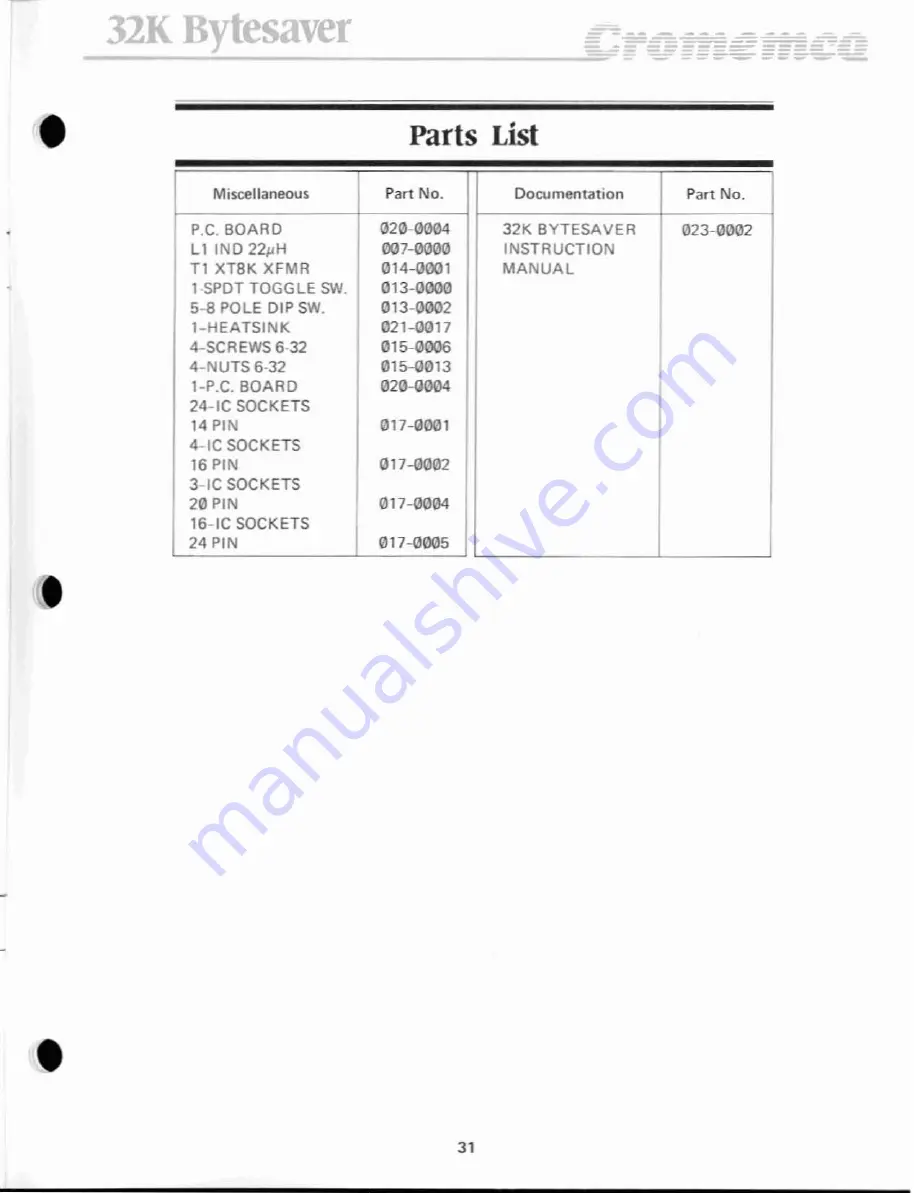
Page 40: ...NO 22pH 007 0lJOO INSTRUCTION T1 XTBK XFMR 014 0001 MANUAL 1 SPOT TOGGLE SW 013 0000 5 B POLE OIP SW 013 0002 l HEATSINK 021 0017 4 SCREWS 6 32 015 0006 4 NUTS 6 32 015 0013 l P C BOARO 02lJ llOO4 24 IC SOCKETS 14 PIN 017 0001 4 IC SOCKETS 16 PIN 017 0002 3 IC SOCKETS 20 PIN 017 0004 16 IC SOCKETS 24 PIN 017 0005 31 ...

Page 41: ...32K Bytesaver ParlsLocationDiagram 7 IS1 H M Of IN UH CJl 32 ...

Page 42: ...ET Pf OGAAN IoIING OFF OlSA8LE SOCkET P RAM NG J llt ITE t tl I 12J4 67 1 BBBBBBB DOW SOC L J ON AEMOVE SOCKET P IR FROM MEMORY MAP OFF SOCKET PAIR IN MEMORY MAP BANK SELECT ON LOGICALLY PLACE BOARD It4 BANK OFF BOARD LOGICALLY t40T IN BANK n SWITCH NUMBER FUNCTION 1 3 NOT USED 4 BANK ON ENABLED ENABLED DISABLED OFF DISABLED 5 WAIT STATE ON ONE WAIT STATE OFF NO WAIT STATES 6 Al5 ON A15 11 OFF IA1...

Page 43: ...nd adequately packaged for shipment to Insure against loss Cromemco Inc reserves the right to refuse to repair any pro duct that in the discretion of Cromemco Inc has been subjected to electrical or mechanical abuse or not handled with reasonable care The service fee is currently 70 and IS subject to change without notice Cromemco Inc makes no further warranties either expressed or implied with re...

Page 44: ... I db I c s 8 s e or e __ _ _ I_ s s t s s e fr J B S o l _ I I L t I l j 7 I 1 t I _ 0 _ ...

Page 45: ... l et4 e Ju 321 8 tu4 C f P CI IOlOEOOl D _ I 1tIill Y r c r _ _ _ _ _ I f _ b a 1 B S B ...

Page 46: ...023 0002 ...

Reviews: