F
LEXIBLE
MULTIPLEXER
E1-XL
1234567890123456789012345678901212345678901234567890123456789012123456789012345678901234567890121234567890123456789012345678901212345678901234567
1234567890123456789012345678901212345678901234567890123456789012123456789012345678901234567890121234567890123456789012345678901212345678901234567
Copyright © 2001 Cronyx
22
Alarm interface
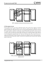
Alarm interface is used to activate an external
alarm device (e. g. a bell, buzzer, panel indicator
etc.) when a failure occurs, e. g. loss of carrier,
loss of synchronization, power failure etc. The
activation is executed using «dry» relay contacts
(i. e. the contacts not linked to any electric circuits
of the modem). The interface also has a pair of
input pins. The state of the pins (closed/open) is
transmitted to the remote device turning on the
relay. If the multiplexer is installed in an
unattended room these input pins can be used for
connection of e.g. remote climatic sensors, door
unlocking signals etc.
Warning! The input pins should be connected
with a switch isolated from electric circuits.
Failure to comply with this requirement may
damage your multiplexer.
When power supply and the carrier are present
pin 3 is shorted to pin 1. At a power failure or a
loss of the carrier pin 3 gets disconnected from
pin 1 and shorted to pin 2 (an alarm state).
External input contacts has two operation modes:
normally open and normally closed. The default
setting is normally open mode. When pin 5 gets
shorted to pin 4 the remote device switches to an
alarm state.
You can set the normally closed mode from a
console in which case the sensor should be
normally closed and its opening causes an alarm
at the remote device.
Alarm circuit
diagram
Alarm state is shown
External input sensor (CPE)
3
5
1
6
2
4
+5v
Alarm connector of /B design
6
4
2
1
3
5
Pin
1
Shorted to the common pin (3) in
normal operation state. Open when an
error occurs.
2
Open in normal operation state.
Shorted to the common pin (3) when
an error occurs.
3
Common pin
4
GND
5
Input pin
6
GND
Back panel connectors
There are digital interface connectors and
removable terminal blocks of E1 links located
on the back panel.
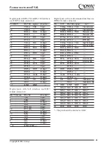
Digital ports with V.35 interface use standard M-
34 female connectors:
DB-25
RS-232
Direction
P
TD-a
Input
S
TD-b
Input
R
RD-a
Output
T
RD-b
Output
U
ET-a
Input
W
ET-b
Input
Y
TC-a
Output
AA
TC-b
Output
BB
ERC-a
Input
Z
ERC-b
Input
V
RC-a
Output
X
RC-b
Output
C
RTS
Input
H
DTR
Input
E
DSR
Output
D
mode
Output
F
DCD
Output
A
CGND
—
B
SGND
—


