- 29 -
5. PLC INTERFACE
5.1 Connection
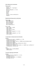
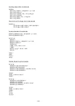
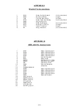
Connection to the PLC or similar device is made via the 25-way ‘D’ connector on the
rear panel. See Appendix IV for pin details.
5.2 Front Panel Set-up
Press MENU on the front panel, select Rem I/F, then press PLC. The PLC is now
selected, and the option to select the Analogue Output is given. This should be OFF if
not required, as it will cause a small incr ease in measurement times. For this reason,
it defaults to OFF at power up. Note that once the Analogue Output is ON, there is no
need for the PLC interface to remain selected, if it is not required.
If no PLC card is fitted, the warning message “** OPTION NOT AVAILABLE **” is
displayed.
5.3 Interface Functions
The PLC interface allows basic remote control of the microhmmeter by a
Programmable Logic Controller or similar device. The facilities it provides are:
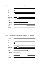
Triggering of measurements.
Selection from 10 stored set-up memories, which are user-programmable via the
front panel (See main Operation Manual for details).
Outputs give indication of ‘End of Test’, ‘Measurement within limits’,
‘Measurement too Low/High’ and ‘Error’.
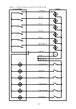
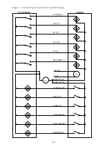
25VDC output available to drive inputs and outputs for a self-contained system.
(For the DO5001 model, it is only avail able when the instrument is connected to
the mains, and is not supplied by the internal batteries).
The analogue Output produces a voltage proportional to the measured resistance
value. If the Temperature Compensation is selected, then this value will be the
compensated resistance.
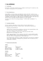
5.4 Electrical Characteristics
Inputs:
Number
7
Type
optoelectronic
Input resistance
1.5 kohms
Minimum voltage
11 VDC or 8 VAC
Maximum voltage
43 VDC or 30 VAC
Outputs:
Number
6
Type
dry contacts
Maximum voltage
70 VDC
Switch rating
30 W
Maximum current
0.15 ADC

