background image

4.9.3  

TRIGGER:

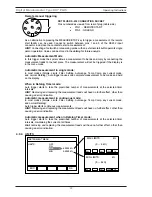
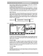
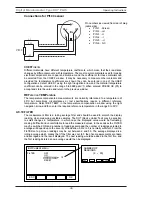
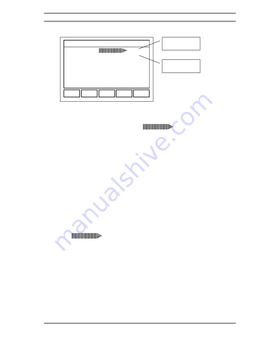
Fig. 4.9.1 

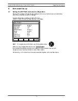
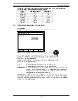
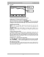
The DO7PLUS measurement can be triggered in several ways. 

Setting Single or Continuous Measurement Mode 

The DO7PLUS may be set to continuous or single measurement mode. 
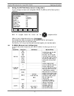
When in the TRIGGER menu window select        

                  Fig: 4.9.1 press the right 

navigation arrow key and then select either SINGLE or CONTINUOUS. Once this mode is set 
it will apply to both the manual and automatic trigger modes. Press OK (F5) to accept choice. 

Single Measurement Mode  

When this mode is set, a single pulse measurement will be made and the value held on the 
display.  

HINT:

 This mode is particularly useful when you want to avoid the self heating effect of the 

measurement current.  

WARNING:

this trigger mode is 

NOT 

suitable for measuring inductive samples such as 

transformers or motor windings. For these applications a continuous measurement current 
should be used. 

Continuous Measurement Mode 

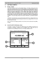
If continuous measurement is selected then the measurement will start when the 
MEASURE/STOP button is pressed. The measurement current will flow continuously in the +I 
and –I current modes and will be continuously switched in the AVERAGE current mode. 
Continuous measurements will be taken and displayed, to Stop the measurement press the 
MEASURE/STOP key and the measurement current will be disconnected and the last 
measured value held on the display.  

Setting Manual or Automatic Measurement Mode 

To set the measurement for manual or automatic triggering select Auto when in the trigger 
menu 

 press the right hand navigation arrow key and then select either 

MAN for Manual triggering or AUTO for automatic triggering. Press OK (F5) to accept choice. 

Manual Measurement Mode 

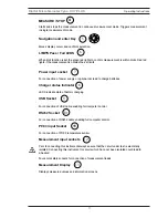
In this mode all measurements are started and stopped manually using the MEASURE/STOP 
key. When the measurement is stopped the measuring current is disconnected and the last 
measured value held on the display. 

INSTRUMENT MENU 

TRIGGER: 

SING 
AUTO 

MEAS

AUTO 

ESC 

OK

SINGLE 
CONTINUOUS 

MAN 
AUTO

MEAS

AUTO

Operating Instructions

Digital Microhmmeter Type DO7 PLUS

21

Summary of Contents for DO7 PLUS

Page 1: ... Microhmmeter Type DO7 PLUS Operating Instructions Bracken Hill South West Industrial Estate Peterlee Co Durham SR8 2SW England Tel 44 0 191 586 3511 Fax 44 0 191 586 0227 www cropico co uk sales cropico co uk ...

Page 2: ...orm or manner either electronically mechanically by photocopying recording or in any manner without prior written consent from CROPICO This also applies to accompanying drawings and diagrams Due to a policy of continuous development CROPICO reserves the right to alter the equipment specification and description outlined in this publication without prior notice and no part of this publication shall...

Page 3: ...ered by the European Directive 2002 96 EC Please familiarise yourself with the appropriate local separate collection system for electrical and electronic products Please dispose of this product according to local regulations Do not dispose of this product along with normal waste material The correct disposal of this product will help prevent potential negative consequences for the environment and ...

Page 4: ...g the DO7PLUS measurement configuration 4 4 Measurement configuration table 4 5 Setting the Range 4 6 Setting the measurement current 4 7 Zero Mode 4 8 Short cut keys 4 9 Menu options explained 4 9 1 Range 4 9 2 Current 4 9 3 Trigger 4 9 4 Limits 4 9 5 Data Log 4 9 6 Statistics 4 9 7 Graphics 4 9 8 Cooling Curve 4 9 9 Temperature Compensation 4 9 10 Filter 4 9 11 Settling 4 9 12 Cable Mode 4 9 13 ...

Page 5: ...urement accuracy is typically 0 05 1 year specification and the value may be displayed with or without temperature compensation The front panel measurement connections are made via 4mm sockets located on the front panel The connection to a Pt100 temperature sensor is made with a Micro Buccaneer 400 series connector For remote control both USB and RS232 interfaces are available which will also enab...

Page 6: ...average values peak to peak value and standard deviation Full QWERTY keyboard for adding notes to logged measurements x RS232 and USB interfaces available for automated monitoring and controlling applications x Graphical display of logged values x Full range of measurement accessories 1 3 Definitions and Terminology n nano Ohm 0 000000001 Ohm P micrOhm 0 000001 Ohm m milliOhm 0 001 Ohm k kilOhm 10...

Page 7: ...losed 1 4 4 Lead resistance The DO7PLUS will operate with long lead lengths providing the maximum lead resistance does not exceed the following Current Leads Maximum resistance 60m each lead 120 m total Potential leads Maximum resistance 1k each lead 2k total 1 4 5 DC Power Input 9 36VDC 4A max 1 4 6 External Mains Power Unit External mains psu 90V 253V 47Hz 63Hz Interchangeable leads Internationa...

Page 8: ...1 4 8 Weight and Size Size 358 x 269 x 155 mm W D H Weight 6 0 kg instrument only Weight Packed 8 5kg Operating Instructions Digital Microhmmeter Type DO7 PLUS 7 ...

Page 9: ...ved while operating or servicing this instrument Failure to comply with these precautions may result in personnel injury or death LIVE CIRCUITS DANGER Do not connect the power supply to or operate this instrument with the protective covers removed Component replacement and internal adjustments must be made by qualified service personnel Do not replace components with the power cable connected Unde...

Page 10: ...rews and sealing washers and store in a safe place Carefully lift out the front panel together with the main measuring unit Remove both plugs from the battery pack by simply pulling them out Place the unit safely to one side Remove the 3 screws and sealing washers from the rear of the case and store in a safe place The battery pack can now be lifted out of the case Place the new battery pack Cropi...

Page 11: ...w to use the keys to configure and operate the DO7PLUS refer to section 4 Key Symbol Description Function F1 RANGE Manual or automatic range can be set F2 CURR Current mode can be selected I I Average or Zero F3 MENU Displays all measurement configuration details F4 SET UP Displays DO7PLUS configuration including date time language etc F5 EXIT ADD NOTE If datalog is on has one or more entries allo...

Page 12: ... LEDS indicate state of battery charging USB Socket For connection of USB cable enabling full computer control RS232 Socket For connection of RS232 cable enabling full computer control Pt100 input Socket For connection of Pt100 temperature sensor Measurement input sockets Prior to connecting this instrument always ensure that the circuit under test is electrically isolated Connecting this instrume...

Page 13: ...ropico service centre for investigation and rectification The power supply should not be opened dismantled or mechanically interfered with In addition to the mains power supply provided with the DO7PLUS a charging lead with car style plug is available as an option enabling the DO7PLUS to be charged with 12 or 24 Volts DC whilst away from base Note To ensure correct charging operation the DO7Plus m...

Page 14: ...temperature compensation mode Function Window Displays x Trigger mode selected x Limits status OFF Hi Lo OK x Filter settings x Settling settings x Data Log Status x Timer if active Status Window Displays x Battery charge state in of full charge x Memory number x Remote status x Measure Stop condition Function Soft Keys x Five soft keys give access to setup menus A B C D Operating Instructions Dig...

Page 15: ...n use the navigation arrows Where an item is highlighted with an arrow this indicates that additional options are available for that parameter and the right navigation arrow should be pressed to reveal those options The table Fig 4 2 1 below shows the options available together with a brief description BACKLIGHT SETUP MENU EXIT BACKLIGHT 60 SECS AUTO OFF 15 MIN KEY BEEP OFF BEEPER ON DATE FORMAT D...

Page 16: ... be selected DATE 28 04 08 Correct date may be entered 11 37 TIME HH MM Correct time may be entered ENG Selects English Language FRA Selects French Language LANGUAGE DEU Selects German Language 50Hz Selects 50Hz line frequency LINE FREQUENCY 60Hz Selects 60Hz line frequency qC Selects qC temperatures for display TEMPERATURE UNIT qF Selects qF temperature for display 9600 BAUD RATE 19200 Selects in...

Page 17: ...automatic range selection AUTO1 selects automatic ranging starting with the 6k range AUTO2 selects automatic ranging starting from last selected range I Selects measurement current in positive direction I Selects measurement current in negative direction AVERAGE Measures with I then with I and displays average CURRENT MODE ZERO Measures emf in circuit and deducts from measurement SINGLE Single pul...

Page 18: ...ith Pt100 external probe TEMP MANUAL Temperature Enter temperature manually Cu 3930 Temperature coefficient of copper 3930ppm qC Al 4030 Temperature coefficient of Aluminium 4030ppm qC USER 1 Coefficient Enter temperature coefficient COEFF USER 2 Coefficient Enter temperature coefficient TEMP COMP REF TEMP Reference temperature Enter temperature 0 to 50qC OFF Switches FILTER OFF ON Switches FILTER...

Page 19: ...hanged more frequently than others and these may accessed directly to change the RANGE settings PRESS F1 and the following screen will display F1 RANGE The F1 function key will take you straight to the range set up menu HINT To navigate around the screen use the navigation arrows To select the highlighted range PRESS OK F5 or the carriage return key Pressing the left arrow will return you to the m...

Page 20: ...e Pressing F1 ESC escapes the range menu and returns to the measurement screen without updating the range I The measurement current flows in the positive direction I The measurement current flows in the negative direction AVERAGE The measurement is made with I current then a second measurement with I current and the average value of the two measurements is displayed The average measurement will el...

Page 21: ...wed by continuous normal measurements until the measurement is stopped If the measurement is restarted then another zero measurement is made followed by continuous measurements If a range change is made either manually or by the auto range function or a measurement error occurs then a new zero measurement will be performed 4 8 Short cut keys enable quick access to menus Short cut Key Function Menu...

Page 22: ...ment is selected then the measurement will start when the MEASURE STOP button is pressed The measurement current will flow continuously in the I and I current modes and will be continuously switched in the AVERAGE current mode Continuous measurements will be taken and displayed to Stop the measurement press the MEASURE STOP key and the measurement current will be disconnected and the last measured...

Page 23: ...ed number of measurements at the selected timer intervals HINT Removing and replacing the measurement leads will have no further effect other than causing an error indication Automatic measurement in continuous mode In most modes Simple Limits Filter Settling Autorange Temp Comp any current mode and normal Datalog Auto trigger starts continuous measurements HINT Removing and replacing the measurem...

Page 24: ...mit and Lo for values below 4 9 5 DATA LOG The DO7PLUS comes complete with a Data Logging facility Up to 1000 readings may stored with date and time stamp Readings may be stored manually or logged using the built in timer Logged values can be reviewed in either graph or table format and statistical analysis of the stored values may be displayed Number Readings To select the number of readings to b...

Page 25: ...ly taken on the first measurement unless autorange changes the range REVIEW Fig 4 9 5 review screen of data logged values The logged measurements can be displayed in a table format Fig 4 9 5 with date and time The log can be scrolled through using the navigation arrows and the highlighted entry can be selected with the right arrow navigation key notes can then be added to the entry using the keybo...

Page 26: ...ta numbers in the FROM TO dialog box and PRESS F5 OK to accept To select the graph type PRESS F2 MODE the dialog box allows the following selection x SCATTER x LINEAR x LINE FIT x COOLING CURVE For the COOLING CURVE additional data needs to be set up but for the other three options the graph is automatically formatted and displayed From the GRAPHICS window the STATS F4 can also be displayed for th...

Page 27: ...r a motor winding this is normally copper This is automatically selected from the coefficients set in the TEMPerature COMPensation Mode which must be switched ON NOTE When the temperature compensation is switched on then AMBIENT TEMPerature and Tnom will be the temperature compensation reference value normally 20qC Fig 4 9 8 Cooling Cuve display IMPORTANT When datalogging readings for use with the...

Page 28: ...t to either MANUAL or Pt100 If the Pt100 option is selected then the ambient temperature will be measured with a Pt100 temperature sensor available as an option If the Manual option is selected using the right navigation arrow then a new window permits the entry of the required temperature over the range 0 to 100qC HINT Once the manual temperature is selected this temperature value is used for all...

Page 29: ...the range 0 to 50qC 4 9 10 FILTER The measurement filter is a rolling average filter and should be used to smooth the display reading when measuring unstable samples The DUT Device Under Test may be sensitive to small changes in temperature in which case the displayed value would be fluctuating making it difficult and uncomfortable to read the measured values In these cases the FILTER may be switc...

Page 30: ...t value is displayed SETTLING LIMIT Highlight and select using the right navigation arrow LIMIT and enter the number of digits in the range 1 to 999 This is the number of display digits by which the number of readings set may differ for the measurement to be defined as settled The settled value will then be displayed If the readings do not then an error message FAILED TO SETTLE will be displayed a...

Page 31: ...per Length of one cable 0 1kOhm 4 Length Unit Metre Kilometre Note that the Length Unit is for display purposes only and no conversion is made from one unit to the other due to under overflow of the calculation 4 9 13 MEMORIES Using the MEMORY function up to 10 DO7PLUS configurations can be stored and recalled Highlight and select MEMORIES using the navigation arrows in the MENU window From this w...

Page 32: ...ree and which are in use Memories can be cleared by pressing CLEAR F4 If a memory is in operation this will be displayed in the Status window if any measurement parameter is sub sequentially changed e g Range then it will no longer be displayed Operating Instructions Digital Microhmmeter Type DO7 PLUS 31 ...

Page 33: ...The instrument is supplied with four leads two for the potential connections which are made across the test resistor at the points between which the resistance is to be determined and two for the current connections which connect the test resistor to the current supply circuit Connect to the resistance under test as shown in figure 5 1 1 Cleanliness is important and if the sample is not clean a ru...

Page 34: ...nection configurations I U U I I I Connections to Current Shunt U P Connection to Cable Joint U U Connections to Stud Terminals I I I U U I Measurement with duplex handspikes Operating Instructions Digital Microhmmeter Type DO7 PLUS 33 ...

Page 35: ... details and part numbers to the front panel socket Select the temperature compensation measurement mode as described in 4 9 9 Alternatively if the ambient temperature is stable a manual value may be entered in this case a temperature sensor is not required The compensated resistance value will be displayed in large digits on the DO7PLUS screen and the true measured resistance value will be shown ...

Page 36: ... options and highlight CAL in the menu HINT To navigate around the screen use the navigation arrows Where an item is highlighted with an arrow This indicates that additional options are available for that parameter and the right navigation arrow should be pressed to reveal those options The display will prompt you to enter a PASSCODE The factory default passcode is 9252 Press F5 OK once the passco...

Page 37: ...ny time you can move back to a previous range with the keys or move forward skipping a range with the keys For simple and easy calibration CROPICO offer a calibration standard model MTS2 which has all the standards required in a single switched unit With the MTS2 true four terminal zero can also be selected Once all the ranges are calibrated for zero and full scale the calibration window then sele...

Page 38: ...mits the updating of the DO7PLUS firmware CROPICO has a programme of continual improvement and firmware updates will be available from time to time These update will be available on CD or may be downloaded from our website www cropico com The updates may be uploaded via the USB or RS232 interface and full instructions will be provided 8 RS232 CONNECTION DIAGRAM DO7PLUS RS 232 CONNECTION SOCKET Pin...

Page 39: ...isting of 4 x 1 metre leads with banana plugs 4 x crocodile clips 4 x test prods and 4 x Kelvin clips KC1 jaw opening 4mm LS06 P Kelvin lead set comprising of miniature Kelvin clips KC2 with 1 metre leads attached terminated with banana plugs Jaw opening 6mm Suitable for fine wires WIRE CLAMPS For the precise measurement of 1 meter cable samples we offer 3 wire clamp options Ordering Code Descript...

Page 40: ...ACE 41 3 1 INTRODUCTION 41 3 2 REMOTE INTERFACE COMMANDS 43 3 3 CONFIGURATION COMMANDS 44 3 4 TRIGGER MEASURE COMMANDS 44 3 5 DATALOG COMMANDS 46 3 6 TEMPERATURE COMPENSATION COMMANDS 47 3 7 MEASUREMENT LIMIT COMMANDS 48 3 8 FILTER ROLLING AVERAGE COMMANDS 49 3 9 SETTLING ALGORITHM COMMANDS 49 3 10 SYSTEM RELATED COMMANDS 50 APPENDICES I Command Summary II RS 232 Pin Connections Operating Instruct...

Page 41: ...l maintain EMC integrity reducing the possibility of interference At the PC end the cable should be connected to a spare Serial COM Port Make a note of the number of this Port if it is labelled FURTHER INFORMATION The port conforms to specification ANSI EIA TIA 232 E 1991 Interface Between Terminal Equipment and Data Circuit Terminating Equipment Employing Serial Binary Data Interchange except tha...

Page 42: ...terface then the USB driver will need to be installed first The driver can be found on the CD supplied with the instrument or can be downloaded from the Cropico website http cropico co uk Follow the installation instructions that accompany the driver Once the driver has been installed the cable should be connected to a spare USB Port on the PC and the instrument switched on The PC should detect th...

Page 43: ...igured correctly for communication to be successful For example if using HyperTerminal press the Disconnect button then click on the File menu Properties select the correct COM Port as described below and click on Configure for the other options For the Cropico DataLogger the Configure option is under the Comms menu which is covered in the DataLogger Help COM PORT This must be set to the correct n...

Page 44: ...O7PLUS as only one command per line can be accepted The semicolon is treated as a non recognised character Whitespace TAB or SPACE A whitespace character must be used to separate the first parameter from a command keyword The DO7PLUS will not accept whitespace characters in the subsequent parameter list Comma If a command requires multiple parameters a comma must be used to separate parameters fro...

Page 45: ...ngle binary value The controller can send OFF or 0 ON or 1 but the instrument response is always 0 or 1 String Parameters contain text as ASCII characters Input Data Format Numeric data sent to the instrument should be in Ohms or Degrees unless stated otherwise The value can be in any standard scientific format e g 3kOhm can be sent as 3000 3E3 3 000E 03 0 3E4 etc The units are not sent Output Dat...

Page 46: ...ted may cause unreliable operation Sending a command whilst the DO7PLUS is transmitting following a command may result in the transmitted response being corrupted It is advisable to wait for the expected response to be transmitted before sending a new command B REMOTE INTERFACE COMMANDS SYSTem REMote Places the instrument in remote mode so that the instrument will respond to other remote commands ...

Page 47: ...if the Settling Algorithm is on SOURce CURRent Returns the measuring current mode currently in force using the appropriate parameter as above D TRIGGER MEASURE COMMANDS These commands set the trigger mode trigger measurements and allow the results to be returned There are basically two methods of triggering a measurement INITiate or TRG command This command triggers a measurement but does not retu...

Page 48: ...erature TCOMpensate Returns the value of the last measurement made This is normally used in conjunction with the INITiate command If in Single trigger mode then INITiate followed by FETCh will be needed for each measurement If in Continuous trigger mode then repeated FETCh commands can be sent to return the most recent measurement One of three optional parameters can be included with this command ...

Page 49: ...e auto trigger state TRIGger DELay hh mm ss Sets the Datalog timer which adds a delay between measurements max 23 59 59 The Datalog must be on Note that if in Continuous trigger mode then the measuring current remains connected during the delay otherwise it is switched off between measurements TRIGger DELay Returns the Datalog timer delay value in the form hh mm ss ABORt Stops the current measurem...

Page 50: ...iation of the resistance values stored in the data log This is effectively a measure of rms noise For example CALC DATA AVER 56 78 will return the average of the Datalog readings from entry number 56 to 78 inclusive CALC DATA AVER ALL will return the average of all of the readings in the Datalog F TEMPERATURE COMPENSATION COMMANDS These commands are used to control the Temperature Compensation fun...

Page 51: ...if omitted will remain at the existing value If it is entered the value must be in ppm C 0 9999 For example SENS TCOM COEF USER2 4100 sets the coefficient to USER2 which is given a value of 4100 ppm C SENSe TCOMpensate COEFficient Returns CU fixed copper coefficient or AL fixed aluminium coefficient or USER1 user1 coefficient or USER2 user2 coefficient The coefficients are quoted in ppm C SENSe TE...

Page 52: ...les the Settling function SENSe SETTling STATe Returns 0 OFF or 1 ON SENSe SETTling COUNt No of readings Sets the maximum number of readings to be taken 2 999 SENSe SETTling COUNt Returns the maximum number of readings selected SENSe SETTling LIMit No of digits Sets the maximum number of display digits 1 999 by which two consecutive readings may differ for the measurement to be defined as settled ...

Page 53: ...mat SYSTem DATE yyyy mm dd Sets the system calendar date SYSTem DATE Queries the system calendar date Returns yyyy mm dd SYSTem DATE FORMat DD MM YY or MM DD YY Sets the date format for the Datalog output for example SYSTem DATE FORMat Queries the date format Returns DD MM YY or MM DD YY DISPlay BRIGhtness ON OFF or 1 0 or AUTO delay value Turns the front panel display backlight on or off or to an...

Page 54: ...urements Auto trigger mode Off Limits Off Datalog Off Temperature Compensation Off Filter Off Settling Algorithm Off Cable mode Off All other functions and parameters are left unchanged by RST TST Always returns 0 to indicate self test OK WAI This command is accepted but ignored as all commands are executed sequentially It is provided only for compatibility with IEEE 488 2 Operating Instructions D...

Page 55: ...IGger DELay ABORt DataLog Commands MEMory DATA CLEAr DATA COUNt No of readings DATA COUNt DATA STATe ON OFF or 1 0 DATA STATe DATA first Datalog entry number last Datalog entry number ALL DATA POINts CALCulate DATA MINimum DATA MAXimum DATA AVERage DATA PTPeak DATA SDEViation Temperature Compensation Commands SENSe TCOMpensate STATe ON OFF or 1 0 STATe MODE EXT or MAN manual temperature MODE REFer...

Page 56: ...SENSe SETTling STATe ON OFF or 1 0 STATe COUNt No of readings COUNt LIMit No of digits LIMit System Related Commands SYSTem REMote LOCal BEEPer BEEPer STATe ON OFF or 1 0 BEEPer STATe VERSion TIME hh mm ss TIME DATE yyyy mm dd DATE DATE FORMat DD MM YY or MM DD YY DATE FORMat DISPlay BRIGhtness ON OFF or 1 0 or AUTO delay value DISPlay BRIGhtness s IDN RST TST WAI Operating Instructions Digital Mi...

Page 57: ...mote Start input 2 RXD Received Data input 3 TXD Transmitted Data output 4 not connected 5 GND Signal Ground 6 not connected 7 RTS Request To Send output 8 CTS Clear To Send input Operating Instructions Digital Microhmmeter Type DO7 PLUS 56 ...

Page 58: ... Tel 44 0 191 587 8718 For Service and Calibration Contact Service Department Seaward Group Unit 11 Bracken Hill South West Industrial Estate Peterlee Co Durham SR8 2LS England Tel 44 0 191 587 8739 Fax 44 0 191 587 8737 E mail service seaward co uk G R O U P CROPICO is a division of SEAWARD ...

Page 59: ... RESISTANCE STANDARDS DIGITAL THERMOMETERS THERMOCOUPLE SIMULATORS PT100 SIMULATORS INSULATION TEST SETS UNIVERSAL CALIBRATORS HIPOT TESTERS ELECTRICAL SAFETY TESTERS Phone fax or e mail for further information on the above or for a copy of our general catalogue Phone 44 0 191 5863511 Fax 44 0 191 5860227 E mail sales cropico com Website www cropico com ...

Page 60: ...551A550 Rev 3 ...
Reviews: