CROPICO LTD – DO7
Issue 7/2001
9
10. POWER
UP
When the DO7 is first switched on, a lamp test is automatically performed. All display segments
are illuminated followed by each LED lighting in sequence. NOTE the LOCK LED is not fitted and
will therefore will NOT light. The microprocessor checks for correct internal operation and indicates
"P" if all tests pass O.K. At the same time the software version will be displayed and held for
approximately 2 seconds. The display will typically read "P 1.1". Should the internal checks
indicate an error, then the display will read "HELP". Contact our Service Department or your local
agent for assistance.
The DO7 will perform an automatic zero sequence and finally sets to the following default start-up
mode ready for use. The selected measuring range will be 60
Ω
, and the DO7 will then be in
stand-by mode.
11. MEASUREMENT
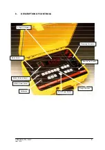
Connect the resistance to be measured (Rx) to the measuring terminals in accordance with the
diagram on the instrument panel. Select the range required, the measurement mode, ie. +, - or
average. The LED lamp will light to indicate which buttons are active. To initialise the
measurement, press and hold the ON button, the measurement will cease once this button is
released and the instrument will return to the STANDBY state. Should you wish to initialise a
continuous reading, then press the LOCK + ON buttons. The measurement will continue until the
STANDBY button is pressed or the ON button pressed again. An audible BLEEP will sound during
this time to warn the operator that measurement is still in progress, and up to 10 Amps measuring
current is draining the batteries.
DISPLAY HOLD FUNCTION
This works as follows:-
1. When returning to the STANDBY condition the LAST measured value will remain on
DISPLAY for 30 SECONDS and then blank.
This occurs when:
Pressing the STBY key, or
Releasing the momentary ON key, or
Releasing the momentary external footswitch.
2. Pressing any key (except LOCK) during the 30 second period will force the display to
blank and allow normal operation to resume. It is recommended that the STBY key be
pressed to carry out this function.
Over-Range
The display will indicate - - - -.
Select a higher range.
Open Circuit Lead
O/C LEAD will be displayed and the display will indicate - - - - if the instrument detects that the
lead resistance is too high. The C terminals are checked for compliance voltage. Measurement
should not be made if this warning message is displayed. This warning will also be displayed if the
internal protection fuse is open-circuit. When in STANDBY mode this LED will always be lit.
Connections
When making good quality measurements, it is important to ensure that all measuring leads are in
good condition, and less than 0.2 ohms resistance.
Summary of Contents for DO7
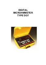
Page 1: ...DIGITAL MICROHMMETER TYPE DO7...
Page 15: ...CROPICO LTD DO7 Issue 7 2001 14...

