background image

CROPICO LTD – DO7

Issue 7/2001

7

The measuring current polarity may be selected from the front panel.  The display will indicate
or - to denote the current flow.  This is particularly useful when evaluating circuits with
thermal emf or where diode effects can influence the measurement.  For measurements where
thermal emf can cause a large measuring zero error, we have provided an additional automatic
average button.  When pressed, the measuring current will automatically be reversed and the
average value displayed, thus eliminating the need for external computations.  This average facility
will also adjust the measurement time automatically, thus giving the fastest possible measurement
even on inductive circuits.

The +ve and -ve lamps will light to indicate that the current polarity is changing. For very unstable
values where the average mode is unable to establish a stable reading, the averaging will be
aborted after approximately 25 seconds and the display will indicate - - - - A new average cycle will
be automatically initialised.

Range Selection:

The 6 ranges may be selected manually by simply pressing the desired range button.  The
selected range will be indicated by an LED and over-range will be indicated by the display reading
- - - -.

Error & Status Lamps

These LEDs will light to indicate the instrument status..

LINE

:

Mains supply is connected to the instrument.

CAL

:

Calibration mode has been initialised by
the key switch and the instrument is in
calibration mode.

O/C 

One of the measuring leads is open circuit

LEAD :

(too high resistance), or not connected to
test sample correctly, or the internal protection
fuse is open circuit.  The lamp will always
light in standby mode.

9.  METHODS OF MEASUREMENT

9.1  Ohmmeter Connections

The Digital Ohmmeter type DO7 employs a four wire method of measurement, ie. it is necessary to
make four connections to the resistor under test.  The instrument is supplied with four leads; two
for the potential connections which are made across the test resistor at the points between which
the resistance is to be determined; and two for the current connections which connects the test
resistor to the supply circuit.

a)  Connect the black leads to the C1 and P1 terminals, and the red leads to terminals

C2 and P2.

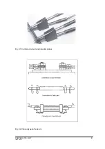
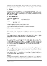
b)  Clip on to the resistor under test (fig. 9-1).  Cleanliness is important and if the sample

is not clean, a rub with an abrasive paper to remove oxides is recommended.

c)  It is not always possible to use the combined current and potential clips, in which

case test leads with spade tags or special test fixtures may have to be made for the
user to suit particular applications.

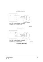
d)  Fig. 9-2 illustrates connections to various types of test resistors.

e)  When measuring 4-terminal resistance standards, do not use the combined current

and potential probes.  Make four separate connections to the current and potential
terminals.

Summary of Contents for DO7

Page 1: ...DIGITAL MICROHMMETER TYPE DO7...

Page 2: ...T 5 7 TECHNICAL DATA 5 8 DESCRIPTION OF CONTROLS 6 Range Selection 7 Error Status Lamps 7 9 METHODS OF MEASUREMENT 7 10 POWER UP 9 11 MEASUREMENT 9 Over Range 9 12 REMOTE 10 13 PRINTER OUTPUT 10 14 PR...

Page 3: ...the apparatus make sure that it is set to the voltage of the power supply The mains plug shall only be inserted in a socket outlet provided with protective earth contact The protective action must no...

Page 4: ...bility is achieved by using our own manufactured internal resistance standards 4 CASE DESIGN The case is ruggedly constructed from an ABS polycarbonate alloy coloured safety yellow A strong internal s...

Page 5: ...use The batteries will recharge in approximately six hours and the DO7 lid should be open to allow for maximum ventilation IMPORTANT Always connect instrument to mains supply after use and top up batt...

Page 6: ...ing currents Measuring time Approx 0 5 seconds Polarity Forward and reverse measurement current may be selected plus average mode which automatically displays the average value of positive and negativ...

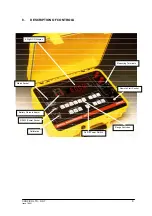
Page 7: ...DO7 Issue 7 2001 6 8 DESCRIPTION OF CONTROLS 4 Digit LCD Display Range Switches On Off Power Switch Calibration Measuring Terminals RS232 Printer Socket Battery Status Indicator Mains Socket Remote S...

Page 8: ...supply is connected to the instrument CAL Calibration mode has been initialised by the key switch and the instrument is in calibration mode O C One of the measuring leads is open circuit LEAD too high...

Page 9: ...CROPICO LTD DO7 Issue 7 2001 8 Fig 9 1 Combined current and potential probes Fig 9 2 Various types of resistors...

Page 10: ...NDBY state Should you wish to initialise a continuous reading then press the LOCK ON buttons The measurement will continue until the STANDBY button is pressed or the ON button pressed again An audible...

Page 11: ...he last value measured when switching from ON to STBY This key toggles ON OFF Baud Rate This key will display the currently set value when pressed To change the value press CLE to clear and then use t...

Page 12: ...ENT REQUIRED Cropico Calibration Standard Type MTS2 Set of 2 low thermal emf leads Set of 2 general purpose leads 10A rating Calibration key no 901 17 PREPARATION 17 1 Ensure all retaining screws are...

Page 13: ...FICATION 19 1 Ensure that the panel switch is set to RUN and the calibration key is removed 19 2 Set the calibration rig to 40 Ohm Zero 19 3 Set the DO7 to 60 Ohm range ve and press LOCK ON Wait for t...

Page 14: ...ay be used in place of the Cropico Calibration Standard The standards must have an uncertainty better than 0 01 if the full calibration accuracy is to be achieved Full consideration of the DO7 measuri...

Page 15: ...CROPICO LTD DO7 Issue 7 2001 14...

Page 16: ...has been detected This test is performed at power up and failure is indicated by the HELP message 21 2 Turn the DO7 power ON Wait for the display test to complete and the HELP message to appear 21 3...

Page 17: ...CROPICO LTD DO7 Issue 7 2001 16...

Page 18: ...e leads HSO2 RS Duplex Handspikes as HSO2 but with remote start button fitted LSO3 Large Kelvin clips with 3 metre leads accept cables and bars up to 38mm diameter LSO4 As LSO3 but with 3 metre leads...

Page 19: ...S THERMOCOUPLE REFERENCE JUNCTIONS THERMOCOUPLE SELECTOR SWITCHES PT100 SIMULATORS PRECISION WATTMETERS INSULATION TEST SETS UNIVERSAL CALIBRATORS POWER ANALYSERS HIPOT TESTERS ELECTRICAL SAFETY TESTE...

Reviews: