background image

23

SECTION 5

OPERATION

BOOM SPRAYING

Some customers will fit out their sprayers with a small boom, 
such as Croplands MBX-04. For further information on 
boom spraying, refer Section 6 - Spraying Information. 

OPERATING POINTERS

While spraying continually observe that:
• Adequate operating pressure is being maintained.
•  Your hand gun coverage is correct and constant for 

effective cover.

• The nozzle is operating correctly.
• Periodically check and clean filters.
•  Avoid going too slow because over application will  

occur. Conversely, avoid going to fast because under 
application will occur.

Tank Agitation

It’s important to use chemicals that remain in solution whilst in a 
spray tank. The tank can only be agitated by the bypass side 
of the Pressure Regulator unit. For this reason, it’s important to 
make sure the pump is generating (slightly) more pressure than 
required for spraying ... if the pump is not generating enough 
pressure there will be no bypass/agitation.

12-VOLT PUMP DUTY CYCLE

12-volt pumps are not recommended for continuous duty 
service due to limited motor brush life. To protect the pump 
from excessive heat, the 12-volt pumps are fitted with a 
thermal cut-out switch.

Once the maximum thermal limit is reached, the motor 
must be allowed to settle to a lower (ideally ambient) 
temperature, before resuming operation.

Running the pump at or near the maximum thermal limit for 
an extended period of time will shorten the life of the pump 
and may result in immediate pump failure. Operation at 
lower pressures and temperatures, however, will extend 
overall pump service life.

EMERGENCY 

ACTION PLAN

Never operate the sprayer  

without an action plan in place for  

when things go wrong ...

“Take 5”

 to evaluate the risks

Actions for most foreseeable 

machine issues such as  

breakages start with ...

“Drop the speed”

“Dump the pressure”

then evaluate further.

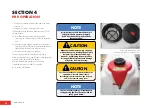
WARNING

!

It is recommended to keep the hose from 

the sprayer on unsprayed ground and 

uncontaminated from the spray.

This minimises contaminants on the hose 

and minimises exposure to chemicals when 

handling and rewinding the hose.

Summary of Contents for Optima US200 CropPak

Page 1: ...T SPRAYERS OPERATORS MANUAL STOP BEFORE COMMENCING operation ENSURE you read understand this manual its contents and any additional information supplied US200F US200F 15 US200F 15 HR US300F 15 US300F...

Page 2: ...nd We welcome any feedback from you about our equipment On the back cover you will find our contact details and locations where our staff can be reached during business hours After hours you can email...

Page 3: ...ng filters draining 18 Before operating for the first time 19 First time start up procedure 12V sprayer 19 SECTION 5 OPERATION 21 Safety first 21 Daily start up procedure 21 Adding chemical to the spr...

Page 4: ...ude damage to the machine itself or possible injury to the operator WARNING This warning sign shows the potential for risk or injury and highlights the need for steps to be taken to protect ones safet...

Page 5: ...ands Warranty policy Always contact your Croplands Dealer first and foremost for warranty matters NOTE For full conditions of warranty and warranty policy please see the Speci cation Safety Warranty D...

Page 6: ...version if available SAFETY SIGNS DECALS All signs and decals for sprayer safety and operation must be maintained in good order and replaced if damaged or missing Most Croplands labels have a part nu...

Page 7: ...ted models are supplied with 10 metre hose reel Controls Standard on the 12 volt models is a pressure regulator mounted on the pump outlet to regulate pressure flow Liquid not required for the boom or...

Page 8: ...e nozzle chosen must be within the flow capability of the pump on your CropPak CropPack sprayers are fitted with pumps that operate within a pressure range For detailed specifications performance char...

Page 9: ...e of flow from approximately 1 litre per minute to 15 1L per minute in the correct pressure range for the pump This pump is used on the US200F 15 and US300F 15 12V CropPak models All CropPak pumps are...

Page 10: ...tch for easy hook up to your battery SECTION 3 PRODUCT IDENTIFICATION SPECIFICATIONS WARNING Ensure your vehicle is rated for the weight of the sprayer when full of liquid Failure to do this may cause...

Page 11: ...illing screen under lid large suction filter pressure filter in lance handle 7 Heavy duty power cable Long heavy duty 12 volt power lead with rockerswitch for easy hook up to your battery 8 Quick clip...

Page 12: ...WARNING Ensure your vehicle is rated for the weight of the sprayer when full of liquid Failure to do this may cause instability serious injury CROPPAK 200 300 LITRE F RANGE 1 2 4 7 6 5 3 LANCE OPTIONS...

Page 13: ...ON US200F New 200 litre CropPak with new galvanised frame on demand 6 8 L min open flow pump 6m spray hose standard with spray lance Power lead with on off switch provided US200F 15 New 200 litre Crop...

Page 14: ...DUCT IDENTIFICATION SPECIFICATIONS 1 2 4 7 8 6 5 9 3 CROPPAK 200 LITRE LANCE OPTIONS WARNING Ensure your vehicle is rated for the weight of the sprayer when full of liquid Failure to do this may cause...

Page 15: ...fitted and hose holders mounted on tank 10 Long heavy duty 12 volt power lead with rocker switch for easy hook up to your battery 1 1 High quality electrical connector to the pump with waterproof plug...

Page 16: ...des connections at the pump end Connect this power cable to a reliable 12 volt battery The red ive power lead to the positive ive battery terminal and The black ive power lead to the negative ive batt...

Page 17: ...el Plumbing for the skid mount F range is very similar but below the tank and the US30 100 S range is much simpler A The suction line from the tank B Suction Filter Check frequently and especially at...

Page 18: ...s are fitted with a filter It s important to use them and keep them clean A careful common sense approach to water quality mixing of chemicals and care of filters hoses and tank will ensure trouble fr...

Page 19: ...RV to the tank Hold down the hand grip lever of the spray lance spray gun Once the unit is spraying clean water adjust the Pressure Regulating Valve red knob position C to the desired pressure using t...

Page 20: ...rom the battery After the initial start up procedure is successfully completed the sprayer is ready for operation Go to section 5 Operation NOTE It is important to check that the pump is fully primed...

Page 21: ...AY TANK The steps for adding chemical to the tank are 1 Calculate the amount of chemical required 2 Part fill the spray tank with water 3 Measure and pre mix the chemical 4 Add the pre mixed chemical...

Page 22: ...hand gun spray lance Aim the nozzle at the target area and hold down the hand grip lever to spray the target Hold down the hand grip lever to spray and check that the o Spray pattern is even o Pump pr...

Page 23: ...no bypass agitation 12 VOLT PUMP DUTY CYCLE 12 volt pumps are not recommended for continuous duty service due to limited motor brush life To protect the pump from excessive heat the 12 volt pumps are...

Page 24: ...sly To use the tank equipment cleaner Fill the spray tank approximately half full of freshwater Add cleaning agent use according to the manufacturer s instructions Switch on the pump Place the lance i...

Page 25: ...tion are measured and controlled Distance time working width are measured Liquid chemical volume applied This is done through sprayer calibration Sprayer calibration is one of the single most importan...

Page 26: ...ard electrical loom Part of the calibration process is to determine the maximum flow required to meet the required target spray rate and this information can be used to determine what speed of travel...

Page 27: ...ality falls into a droplet range of Ultra Coarse Extremely Coarse Very Coarse Coarse Medium Fine Very fine It is more important than ever that the agricultural industry demonstrates responsible chemic...

Page 28: ...ray lines Never leave chemicals in the tank or the pump Rinse the tank out completely with fresh water and operate machine to clear all spray lines Remove boom tube caps if you have a boom fitted and...

Page 29: ...nnection 2 Replace fuse 3 Repair loose wiring or connection 4 Replace pressure switch 5 Replace motor or rectifier 6 Repair or replace cam bearing C Low Flow and Pressure 1 Blocked suction filter 2 Ai...

Page 30: ...refer to sprayer for actual plumbing Parts listed are indicative of the sprayer type Items in italics or without a part number are non stocked items and may need to be specially ordered For further pa...

Page 31: ...SECTION 8 ASSEMBLY DRAWINGS PARTS SCHEMATICS 50 GP OMCP12 C NOTE For the latest pump drawings and specifications see the Croplands website and go to the Sprayer Components section 50 GP OMCP12 C Floj...

Page 32: ...ATURE NAME DEBUR AND BREAK SHARP EDGES FINISH UNLESS OTHERWISE SPECIFIED DIMENSIONS ARE IN MILLIMETERS SURFACE FINISH 0 2 TOLERANCES LINEAR 0 5 ANGULAR 0 5 Q A MFG APPV D CHK D DRAWN COPYRIGHT PROPRIE...

Page 33: ...E 1 1 1 UP 416 BOAT PLUG 1 12 UP 501 S BEND HOSE EPDM BLACK 1 13 COBRAC18 198 COBRAC CLAMP 1 2 RED HOSE 1 14 TR38HC HOSE CLAMP 10MM 3 8 WORM DRIVE 3 15 M6X30 M6 X 30 SET SCREW HT ZP 4 16 M6FWASHER M6...

Page 34: ...ONG 1 7 FL20381 000 KIT 1 2 THREAD STRAIGHT PAIR 1 8 FL3521 139 PUMP 12V 60PSI 15 1LT SANTO VITON 1 9 P100D RAW TANK 100LT POLY CROPPAK VERSION 2 1 10 SW501 004 LID STRAINER 1 1 1 SW502 001C TANK LID...

Page 35: ...HPW10 HOSE 6 SW808 073C VALVE 1 SW803 262C JET 1 SW803 085 LANCE 1 HPW12 HOSE 1 COBRAC15 8 CLAMP 2 SW501 004 STRAINER 1 UP 169 PIPE 1 SW502 001C LID 1 UP 175 HOOK 4 UP 416 PLUG 1 B163 604 13 ELBOW 1...

Page 36: ...25 M6 X 25 SET SCREW HT ZP 4 21 M6FWASHER M6 FLAT WASHER ZP 5 22 M6NNUT M6 NYLOC NUT HT ZP 1 3 2 1 5 C D 4 6 7 8 A B CROPPAK 200LT 15LPM PUMP 21 06 2022 N A TITLE REVISION DO NOT SCALE DRAWING DATE SI...

Page 37: ...TITLE REVISION DO NOT SCALE DRAWING MATERIAL DATE SIGNATURE NAME DEBUR AND BREAK SHARP EDGES FINISH UNLESS OTHERWISE SPECIFIED DIMENSIONS ARE IN MILLIMETERS SURFACE FINISH 0 2 TOLERANCES LINEAR 0 5 AN...

Page 38: ...5 8 9 4 US200 FM2 PA THIS DRAWING IS FOR PLEASE REFER TO THE ITEM NO PART NUMBER D 1 AS GUNCLIP GUNCLIP WITH S 2 B165 1501 5 BALL VALVE 1 2 X 3 P200C RAW TANK 200LT RTV 4 P200C 6L RAW TANK 6LT RTV HA...

Page 39: ...12 DWG NO TITLE REVISION DO NOT SCALE DRAWING MATERIAL DATE SIGNATURE NAME DEBUR AND BREAK SHARP EDGES FINISH UNLESS OTHERWISE SPECIFIED DIMENSIONS ARE IN MILLIMETERS SURFACE FINISH 0 2 TOLERANCES LI...

Page 40: ...able nozzle F SW219 143C Spray lance 150cm plastic c w adjustable nozzle G SW219 146C Spray lance 200cm plastic c w adjustable nozzle H SW219 282C 4 Nozzle boom 150cm plastic I SW219 151C 3 Nozzle boo...

Page 41: ...s 28 Manuals 4 Nozzle selection 25 26 27 Nozzle adjustment 19 Nufarm 2 27 Nozzle selection 25 26 27 Operational pointers 23 Operator training responsibilities Safety manual Parts lists Section 8 p 32...

Page 42: ...l sales croplands com au Website www croplands com au NEW ZEALAND Croplands Equipment Ltd PO Box 2004 Stortford Bridge Hastings 4120 Location 1422 Omahu Road Hastings 4120 New Zealand Freecall 0800 10...

Reviews: