2.23
Pinto BT-POM 1212 - Revision 5
Section 2
b) Check MT3405 Controller
Operation (if fi tted)
The automatic Spray Controller controls all
aspects of the spray application rate.
Set the rates you want and the Controller
ensures constant application rate -
irrespective of undulating terrain, engine
speed, ground speed and variations in
nozzle wear.
To operate the unit:
1 Connect Pinto to tractor (see
instructions pages 2.10).
2 Fill an appropriate quantity of clean
water into main tank (see instructions
pages
3.2).
Pre-Operation Check - 3000 Litre
3 Check that the Suction Selector Valve
is set for the main tank.
4 Check the Function Selector Valve is
in "Spray" position.
5 Follow the instructions in the
Spray Controller Instruction
Manual - to calibrate and operate
the
Controller.
6 Place the master switch of the
Spray Controller in OFF position
for start up. Ensure the controller
power switch is ON.
7 Engage the PTO and bring the PTO
(pump) speed up to 540 RPM.
In the case of a hydraulic drive,
engage the appropriate hydraulic
remote.
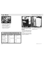
(5) Enter the fl ow meter calibration factor.
MT3405 Controller - optional.
Additional copies of the Spray Controller manual
can be downloaded in a PDF fi le format from the
Internet.
For the micro-trak MT3405 or MT900 controllers, log
onto www.micro-trak.com and follow the menu.
NOTE
8 Adjust the spraying pressure as
follows with the tractor & sprayer
stationary:
(a) On the Spray Controller, select
the MANUAL mode using the
appropriate
key.
(b) Switch on all boom valves, and
switch the controller into the
“RUN” position. Water will now be
fl owing out the nozzles.
It is recommended to do this with
the boom open in the spraying
position.
(c) Use the “+” key on the Spray
Controller to fully close the
electric servo valve. This will take
a few seconds.
(d) When the servo is fully closed,
adjust the Pressure Regulator
valve as shown to the maximum
working pressure. In the case of
the Pinto, we recommend the
maximum working pressure be
set at 8 BAR (120 psi).
If the maximum pressure is
above this, damage to your
sprayer may result.
To properly check the controller operation, unfold
the boom and complete steps 1 - 16.
NOTE
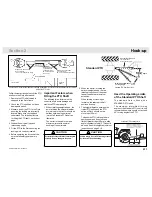
(8[d]) Adjust the Pressure Regulator valve.
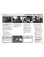
(4) Check the Function Selector Valve is in Spray position.
(3) Suction Selector Valve set for the main tank.
Summary of Contents for Pinto 2000
Page 1: ...Pinto Parts Operator s Manual Pinto Part No BT POM00210 Rev 5...
Page 11: ...1 8 Pinto BT POM 1212 Revision 5...
Page 13: ...1 10 Pinto BT POM 1212 Revision 5...
Page 18: ...2 5 Pinto BT POM 1212 Revision 5 Section 2 Safety Please order replacements if required Decals...
Page 88: ...5 3 Pinto BT POM 1212 Revision 5 Section 5 Grease Point Diagrams Boom Grease Points...
Page 109: ...7 2 Pinto BT POM 1212 Revision 5 Assembly Drawings Parts AR135 Pump...
Page 132: ...7 25 Pinto BT POM 1212 Revision 5 Section 7 Plumbing Diagram AR160 AR135...
Page 136: ...7 29 Pinto BT POM 1212 Revision 5 Section 7 Electrical Diagram Optional MT3405F 4 4...
Page 147: ...7 40 Pinto BT POM 1212 Revision 5 Assembly Drawings Parts GBNEWE 18 21C Centre Section 16 21m...


