3.17
Pinto BT-POM 1212 - Revision 5
Section 3
Hydraulic Boom Set-Up
The initial boom alignment is carried out at the
factory and checked by your dealer.
NOTE
Boom Set-Up
The boom requires adjustment for optimum
operation and wear life:
1 The boom assembly requires:
(a) Wing alignment.
(b) Wing extension alignment.
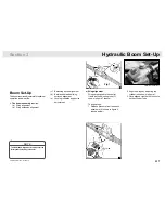
a) Wing alignment
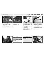
Wings are aligned to the central
frame via the adjusting rods (C)
shown in fi gure 1 (above).
To align wings:
1 Release pressure from the shock
absorbers (A) shown in fi gure 2
(shown
below).
2 Align the wings by adjusting the
cylinder rods shown in fi gure 1.
3 Once aligned, tighten the lock nuts
on the cylinder rods.
Fig 1
Adjust the cylinder rods.
(c) Balancing device alignment.
(d) Backlash between sliding
surfaces alignment.
(e) Locking the balancing device
adjustment.
Summary of Contents for Pinto 2000
Page 1: ...Pinto Parts Operator s Manual Pinto Part No BT POM00210 Rev 5...
Page 11: ...1 8 Pinto BT POM 1212 Revision 5...
Page 13: ...1 10 Pinto BT POM 1212 Revision 5...
Page 18: ...2 5 Pinto BT POM 1212 Revision 5 Section 2 Safety Please order replacements if required Decals...
Page 88: ...5 3 Pinto BT POM 1212 Revision 5 Section 5 Grease Point Diagrams Boom Grease Points...
Page 109: ...7 2 Pinto BT POM 1212 Revision 5 Assembly Drawings Parts AR135 Pump...
Page 132: ...7 25 Pinto BT POM 1212 Revision 5 Section 7 Plumbing Diagram AR160 AR135...
Page 136: ...7 29 Pinto BT POM 1212 Revision 5 Section 7 Electrical Diagram Optional MT3405F 4 4...
Page 147: ...7 40 Pinto BT POM 1212 Revision 5 Assembly Drawings Parts GBNEWE 18 21C Centre Section 16 21m...


