background image

4.13

Pinto BT-POM 1212 - Revision 5

Section 4

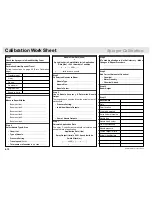
Calibration Work Sheet

Nozzle Flow Rate (l/min) 

=                        

Speed (km/hr) x Swath Width (m) x Application 

Rate (l/ha) 

÷

 600 

÷

 Number of nozzles


    ...... x ..... x ..... 

÷

 600 

÷

 .......


=  .......... l/min for each nozzle

Step 5

Fit Selected Nozzles to Boom

  Nozzle 

Type: ...................................................

  Nozzle 

Size: ...................................................

  Nozzle 

Colour: ...............................................

Step  6

Check Nozzle Accuracy & Determine Nozzle 
Output

Thoroughly check nozzles & test the actual output of 
each nozzle.

 • 

Pressure Setting: ..........................................

 • 

Individual Nozzle Outputs: ...........................

  .........................................................................

  .........................................................................

 • 

Sum of Nozzle Outputs: ...............................

Step  7

Calculate Application Rate

The spray Controller automatically calculates and 
shows the rate of application.

Application Rate (l/ha)

=

 Spray Output (l/min) x 600 

÷

 Speed (km/hr) x 

Swath Width (m)

[......... x 600] 

÷

  [........ 

x

 .........]

=     ................

Step 1 

Check the Sprayer is in Good Working Or der 

Step 2

Determine Actual Speed of Travel

Follow Instructions on page 60 (Pinto Calibration 
page). 

 Tractor 

model    


 Gear  


 Range 


 Dual 

power     


 Engine 

RPM     


 Speed 

in 

Km/h

Step 3

Measure Boom Widths


  Boom section 1: .............................................


  Boom section 2: .............................................


  Boom section 3: .............................................


  Boom section 4: .............................................


  Boom section 5: .............................................


  Boom section 6: .............................................

Step  4 

Select Nozzle Type & Size

 • 

Chemical: ......................................................

 • 

Type of Nozzle: .............................................

 • 

Pressure Setting: .........................................

 • 

Travel speed (km/hr): ....................................

 • 

Total number of nozzles to be used .............

Step 8

If Tested Application is Not Satisfactory - Make 
Changes & Repeat Procedure

  .........................................................................

  .........................................................................

Step 9

Add Correct Amount of Chemical

 • 

Chemical: .......................................................

 • 

Water Quantity: ..............................................

 • 

Chemical Added: ...........................................

Step 10

Boom Height

  .........................................................................

Step 11

Record Data

Date

Farm location

Crop to be sprayed  


Spray Volume litres/ha 

Nozzle type 


Nozzle size &colour 


No. of nozzles used

Nozzle pressure 


Tested Output in l/min     

Actual Litres/Hectare   


Summary of Contents for Pinto 2000

Page 1: ...Pinto Parts Operator s Manual Pinto Part No BT POM00210 Rev 5...

Page 2: ...tents Foreword Important Information Section 1 Pre Operation Section 2 Sprayer Operation Section 3 Sprayer Calibration Section 4 Lubrication Maintenance Section 5 Trouble Shooting Section 6 Assembly D...

Page 3: ...nance 2 Read and follow instructions on chemical manufacturers labels 3 Always wear applicable protective clothing Read and understand this Operators Manual before operating the sprayer Terminology Th...

Page 4: ...1 1 1 1 Section 1 Important Information Introduction 1 2 General Specifications 1 3 Your Sprayer s Specifications 1 4 Shipping Information Product ID 1 5 Warranty Policy 1 6 Pre Delivery Check List 1...

Page 5: ...will find our contact details and locations where our staff can be reached during business hours After hours you can e mail us and expect a reply the following morning Please read this manual in its e...

Page 6: ...ease nozzles Corrosion and chemical resistant poly bond finish 16 18 21 24 metre 50 60 70 80 fully hydraulic boom stronger and designed for smoother more accurate spraying and long life Airbag boom su...

Page 7: ...Controller Standard Electric Automatic Spary Rate Controller Foam Marker or Guidance Salvarani Double sided R M2012 20 l min RHS RHS Outback 6 RHS Outback 10 Outback Guidance Fence line nozzle Manual...

Page 8: ...9m x 6 5m x 3 0m 21m boom with boom folded Pinto Serial Number AR Pump Serial Number B A Pinto Serial Number Plate The Pinto Serial Number Plate is located on the main frame at the front of the frame...

Page 9: ...of a sprayer after the discovery of a defect which results in greater damage to the unit Deteriorated or failed components such as diaphragms O rings hoses seals electrical wiring and connections dam...

Page 10: ...sealed 11 Bottom Fill Spray Flush Tanks Check bottom fill operates Filter clean sealed Check hoses properly sealed Check caps plugs in place 12 Nozzles Undamaged Nozzle filters clean Nozzles correct...

Page 11: ...1 8 Pinto BT POM 1212 Revision 5...

Page 12: ...and correct operation of the Sprayer and e Agrees that the Owner will fully train any person who might be required to operate the Sprayer as to how to operate the Sprayer in a safe and proper manner 2...

Page 13: ...1 10 Pinto BT POM 1212 Revision 5...

Page 14: ...into BT POM 1212 Revision 5 2 1 Section 2 Pre Operation Safety 2 2 Hook up 2 10 Unhitching 2 18 Manual Control Valves 3000 Litre 2 19 2000 Litre 2 25 Pre Operation Check 3000 Litre 2 20 2000 Litre 2 2...

Page 15: ...on Needs a Qualified Operator A Qualified Operator Must Do the Following 1 Understand the Written Instructions Rules Regulations The written instructions from Croplands are included in the Pinto Opera...

Page 16: ...loy steels are used in many parts which are important to the equipment design Home made parts may look the same but might be dangerous in operation Follow the chemical manufacturer s precautions befor...

Page 17: ...in original containers and keep them tightly closed Never keep them in anything but the original containers Read labels for hazards about chemical reaction with certain types of metals Do not spill ch...

Page 18: ...2 5 Pinto BT POM 1212 Revision 5 Section 2 Safety Please order replacements if required Decals...

Page 19: ...2 6 Pinto BT POM 1212 Revision 5 Pre Operation Safety Please order replacements if required Decals...

Page 20: ...refully Cut to open do not tear Do not stir chemicals with hands or arms Choose the mixing site carefully the fate of the probable residues Do not mix more spray solution than is needed and avoid need...

Page 21: ...determined by the type of chemicals degree and duration of exposure weather conditions and application equipment used Read and follow the direction on the label Over protection can be uncomfortable a...

Page 22: ...before starting again Ensure that contaminated clothing is washed thoroughly before being used again Don t guess when choosing protective equipment Feel free to call Croplands and make use of our safe...

Page 23: ...sis using the support jack until the correct height is reached c Replace and tighten the hitch height adjustment bolt If removed refit the pump hose 2 Connect the Pinto Hitch PTO Shaft to the Tractor...

Page 24: ...he height difference between the tractor PTO spline and the PTO spline of Pinto should not be more than 100mm This ensures PTO joint angles are approx equal and do not exceed limits If greater than 10...

Page 25: ...ve the boom lock plate see pic This plate is in place for transport to your dealer from the Croplands factory Connect the boom hydraulic hoses to the tractor namely a Boom fold hoses b Boom parallelog...

Page 26: ...r running Ensure your working testing area is clear of bystanders If your sprayer is fitted with a hydraulic pump drive connect the hydraulic hoses to the tractor remotes Please read the following pag...

Page 27: ...motor When the oil is bypassed around a loop and does no work the energy put into it by the pump turns into heat Therefore the amount of oil bypassed should be kept to a minimum Tractor adjustments ma...

Page 28: ...tric controller and cable from the Pinto 2 Place all switches into Off position 3 Fit the controller console into the tractor cab in a convenient and safe location for the operator 4 Connect the contr...

Page 29: ...ed NOTE The loom coupler has locating holes for fixing the plug to the tractor which is recommended Ask you dealer for asssistance if required Likewise if you have an electric hydraulic control consol...

Page 30: ...the Standard Salvarani Double Sided Foam Controller To fit the Salvarani Double Sided Foam Controller 1 Unpack the foam marker controller and cable from the Pinto 2 Install the foam marker controller...

Page 31: ...tive terminal Damage can occur to units if power leads are reversed or incorrectly fitted WARNING 3 Connect and lock the foam marker plugs together Connect the Foam Marker leads to the loom If you are...

Page 32: ...and side of the manual control panel sets the following functions 1 Chem E Flush 2 Spray 3 Tank Rinse 4 Off Chem E flush Option Valves Fresh Water Hand Rinse Tap located above the Bottom Fill Inlet Bo...

Page 33: ...gm pump air chamber is 70 100 kPa 10 15 psi As a general guideline it should be 10 20 of operating pressure Not applicable if fitted with Hypro centrifigal pump 10 Check that the suction and pressure...

Page 34: ...umped liquid is now being passed through the dump valve back into the tank The system is not pressurised and tank agitators are not working 7 Pressurise the system and operate the tank agitator by pla...

Page 35: ...eck the nozzles are operating correctly Rectify any problems 13 With all boom sections operating check operating pressure and make appropriate adjustment 14 Switch booms ON and OFF several times and c...

Page 36: ...nter the flow meter calibration factor MT3405 Controller optional Additional copies of the Spray Controller manual can be downloaded in a PDF file format from the Internet Forthemicro trakMT3405orMT90...

Page 37: ...ting correctly Rectify any problems 13 With all boom operating re check pressure range by alternating from to on the Spray Controller while in MANUAL mode Ensure maximum pressure does not exceed 8 BAR...

Page 38: ...main tank on the left hand side used for sourcing liquid from the Main tank or Flush tank Chem E flush Option Valves Fresh Water Hand Rinse Tap located at the left front corner of the main tank Botto...

Page 39: ...phragm pump air chamber is 70 100 kPa 10 15 psi As a general guideline it should be 10 20 of operating pressure Not applicable if fitted with Hypro centrifigal pump 10 Check that the suction and press...

Page 40: ...ed liquid is now being passed through the dump valve back into the tank The system is not pressurised and tank agitators are not working 7 Pressurise the system and operate the tank agitator by placin...

Page 41: ...eck the nozzles are operating correctly Rectify any problems 13 With all boom sections operating check operating pressure and make appropriate adjustment 14 Switch booms ON and OFF several times and c...

Page 42: ...er the flow meter calibration factor MT3405 Controller optional Additional copies of the Spray Controller manual can be downloaded in a PDF file format from the Internet Forthemicro trakMT3405orMT900c...

Page 43: ...rectly Rectify any problems 13 With all boom operating re check pressure range by alternating from to on the Spray Controller while in MANUAL mode Ensure maximum pressure does not exceed 8 BAR Minimum...

Page 44: ...tion 3 Sprayer Operation Filling 3 2 Foam Marker 3 5 Filters Tank Agitation 3000 Litre 3 9 2000 Litre 3 13 Cleaning 3000 Litre 3 11 2000 Litre 3 15 Boom Set Up 3 17 Chemical Mixing 3000 Litre 3 20 200...

Page 45: ...vated when they contact these materials Always calculate the correct water quantity required and when filling allow sufficient water quantity for adding and mixing chemicals If necessary top up the ta...

Page 46: ...000 Litre To Bottom fill the Flush tank 1 Remove the end cap from the fill inlet connect the filling hose 2 Turn the Fill Selector Valve to the Flushing tank 3 Fill the Flush tank with the amount of w...

Page 47: ...your Pinto is fitted with the optional Salvarani or RHS foam marker fill with clean fresh water preferably rainwater Use the tank lid for top filling and adding foam concentrate To fill foam marker t...

Page 48: ...ng Always add concentrate to water and not water to concentrate when top filling When topping up a tank of mix with a water hose place the end of the hose under the surface so as not to agitate the so...

Page 49: ...fore undoing the cap to refill and when finished for the day 4 Flick the selector switch to the right hand position on the control panel and check that the right hand side foam nozzle is putting out t...

Page 50: ...position Setting Liquid Pressure The foam marker injects the foam liquid mixture under pressure into the air stream to make foam Liquid pressure is adjusted using the in cab control see page 3 6 The...

Page 51: ...ly you won t operate over 55 psi as it will use excessive solution and create a very wet foam In very hot dry conditions it may be necessary to use very wet foam to increase the life of the foam Outba...

Page 52: ...m of the filter to ensure all pressure is removed from the filter 3 Remove the outer filter bowl and then remove the filter and thoroughly clean it before re assembling the filter Suction Filter The s...

Page 53: ...e agitator to reduce foaming If chemical settles through pump break down or another reason start up the sprayer after the fault has been rectified and let the mixture in the tank agitate for a length...

Page 54: ...ayer controls in start up position according to the instructions of the controller fitted 7 Engage PTO and bring the PTO speed up to 540 RPM All pumped liquid is now being passed through the dump valv...

Page 55: ...ng 8 Pressurise the system by placing the Master switch ON and Boom switch number 5 ON 9 Adjust pressure to desired operating pressure by adjusting pressure up or down 10 Turn the spray boom sections...

Page 56: ...e bottom of the filter to ensure all pressure is removed from the filter 3 Remove the outer filter bowl and then remove the filter and thoroughly clean it before re assembling the filter Suction Filte...

Page 57: ...e agitator to reduce foaming If chemical settles through pump break down or another reason start up the sprayer after the fault has been rectified and let the mixture in the tank agitate for a length...

Page 58: ...e sprayer controls in start up position according to the instructions of the controller fitted 7 Engage PTO and bring the PTO speed up to 540 RPM All pumped liquid is now being passed through the dump...

Page 59: ...Pressurise the system by placing the Master switch ON and Boom switch number 5 ON 9 Adjust pressure to desired operating pressure by adjusting pressure up or down 10 Turn the spray boom sections ON F...

Page 60: ...tension alignment a Wing alignment Wings are aligned to the central frame via the adjusting rods C shown in figure 1 above To align wings 1 Release pressure from the shock absorbers A shown in figure...

Page 61: ...inner wings 3 Tighten lock nuts B after alignment is finalised c Balancing device alignment The boom is fitted with an adjustable connecting rod which allows the boom to tilt 0 3 on the horizontal ax...

Page 62: ...erate with the down hillside boom lowered and uphill side boom folded Unfolding folding the Spray Boom Understand the safety precautions below before operating the folding mechanism of the spray boom...

Page 63: ...ha x Spray Application Rate l ha eg 300 x 150 45 000 litres 3 For area covered by a given volume of mixture calculate the area using the following formula Area Covered ha Tank Volume litres Spray App...

Page 64: ...opper lid add chemical powder or liquid to the hopper k Close the hopper lid open the Nozzle Rinse valve to mix chemical l Close the Nozzle Rinse valve when chemical is mixed k Close hopper lid open t...

Page 65: ...of the hopper 2 Chemical Probe To add chemical to the main tank using the chemical probe follow the steps outlined a Make sure sufficient water is added to the main tank and the flush tank b Remove t...

Page 66: ...witch No 5 must be turned ON if pressure is required when the boom is off ie for agitation chemical probe operation NOTE k Disconnect the Probe hose and replace the Probe inlet end cap l Return the Pr...

Page 67: ...ha x Spray Application Rate l ha eg 300 x 150 45 000 litres 3 For area covered by a given volume of mixture calculate the area using the following formula Area Covered ha Tank Volume litres Spray App...

Page 68: ...y placing the Master switch ON switch No 5 ON Keep boom switches OFF j Open the hopper lid add chemical powder or liquid to the hopper k Close the hopper lid open the Nozzle Rinse valve to mix chemica...

Page 69: ...ansfer valve at the base of the hopper 2 Chemical Probe To add chemical to the main tank using the chemical probe follow the steps outlined a Make sure sufficient water is added to the main tank and t...

Page 70: ...into incorporates a relief valve which automatically dumps pressure when the boom is switched off Therefore Switch No 5 must be turned ON if pressure is required when the boom is off ie for agitation...

Page 71: ...g range of the nozzles and application rates selected Operating Methodology for Broadacre Spraying It is always preferable to spray travelling across the wind direction This minimises any drift effect...

Page 72: ...Pinto BT POM 1212 Revision 5 4 1 Section 4 Sprayer Calibration Calibration Procedure 4 2 XR AI TeeJet Nozzle Chart 4 9 Air Mix Turbodrop Nozzle Chart 4 10 Calibration Work Sheet 4 12...

Page 73: ...application rate set by the operator when operated in Auto position The controller monitors speed of travel speed sensor and flow rate flow meter and automatically adjusts flow rate via a servo valve...

Page 74: ...hours of operation 1 Unscrew the sensor 2 Separate the sensor from the Rapid Check unit Wash any impurities out of the removable turbine unit Remove the Rapid Check unit Use compressed air to check t...

Page 75: ...ype Size Select Nozzle Type Size according to Chemical recommendations Application rate required Pressure setting Swath width Chosen speed of travel Use actual speed of travel refer to step 2 Two meth...

Page 76: ...he Selected Nozzles to the Boom Fit the selected nozzles to the boom as per the nozzle manufacturers specifications Step 6 Recommended Check Nozzle Accuracy Determine Nozzle Output Test the actual out...

Page 77: ...tip wear courtesy of Teejet c Collect and measure the volume of spray from one nozzle and adjust pressure so that the nozzle gives the specified output eg 0 5 l min IMPORTANT Do not use a worn nozzle...

Page 78: ...ocedure c For land area covered use the formula Area Covered ha Tank Volume litres Spray Application Rate l ha eg 2000 50 40 hectares d For tank volume required use the formula Tank Volume Required li...

Page 79: ...or soil being sprayed Minimum boom height recommendations depend on the nozzle spray angle and nozzle spacing Refer to Nozzle chart recommendations Step 11 Record All Data For Future Reference Record...

Page 80: ...237 190 158 135 119 94 8 79 0 59 3 52 7 47 4 37 9 31 6 27 1 4 0 0 91 273 218 182 156 137 109 91 0 68 3 60 7 54 6 43 7 36 4 31 2 1 0 0 68 204 163 136 117 102 81 6 68 0 51 0 45 3 40 8 32 6 27 2 23 3 1 5...

Page 81: ...4 0 924 222 185 159 139 111 92 69 56 5 1 033 248 207 177 155 124 103 77 62 6 1 131 271 226 94 170 136 113 85 68 1 0 577 138 115 99 87 69 58 43 35 2 0 816 196 163 140 122 98 82 61 49 3 1 000 240 200 1...

Page 82: ...6 2 263 542 452 388 340 272 226 170 136 1 1 155 277 231 198 173 139 116 87 69 2 1 633 392 327 280 245 196 163 122 98 3 2 000 480 400 342 300 240 200 150 120 4 2 309 556 462 398 348 278 230 172 140 5...

Page 83: ...p 1 Check the Sprayer is in Good Working Order Step 2 Determine Actual Speed of Travel Follow Instructions on page 60 Pinto Calibration page Tractor model Gear Range Dual power Engine RPM Speed in Km...

Page 84: ...idth m x 600 x Step 1 Check the Sprayer is in Good Working Order Step 2 Determine Actual Speed of Travel Follow Instructions on page 60 Pinto Calibration page Tractor model Gear Range Dual power Engin...

Page 85: ...p 1 Check the Sprayer is in Good Working Order Step 2 Determine Actual Speed of Travel Follow Instructions on page 60 Pinto Calibration page Tractor model Gear Range Dual power Engine RPM Speed in Km...

Page 86: ...T POM 1212 Revision 5 5 1 Section 5 Lubrication Maintenance Greasing Service Procedures 5 2 Grease Point Diagrams 5 3 Pumps 5 4 Filters 5 6 Diaphragms Straps 5 7 Foam Markers 5 7 Motor Valves 5 10 Boo...

Page 87: ...her grease points refer diagram on page 5 3 13 Grease the Pinto jack 7 Grease tractor to sprayer PTO universal joints every 8 hours Grease lightly until grease becomes firm in seals Over greasing will...

Page 88: ...5 3 Pinto BT POM 1212 Revision 5 Section 5 Grease Point Diagrams Boom Grease Points...

Page 89: ...th oil before working the pump 2 When changing the pump oil check diaphragms and replace them if they are showing signs of wear This is normally a pre season maintenance procedure which can be done ea...

Page 90: ...iton diaphragms particularly if the pump is not properly flushed after use Pump Storage and Corrosion Protection 1 Warm Climates If you operate in a warm climate with no chance of frost in the winter...

Page 91: ...ge 3 14 If leaking occurs from the nozzle cap check caps are correctly fitted with seals or the condition of the seals Replace if necessary Foam Marker Filter The foam marker filter should be cleaned...

Page 92: ...ve on the tank cap needs no maintenance Operating the pressure discharge ring under the tank cap prevents incrustations forming on the pressure relief valve at the same time checks its efficiency Mach...

Page 93: ...operating the lever selector in the position corresponding to the boom section involved until only air comes out of the diffusors Fit all the parts back together to restore the initial conditions Car...

Page 94: ...ff season use an anti freeze solution rather than a weak foam solution in the above steps NOTE Foam Markers Tank Keep dirt and debris out of the tank at all times The foam marker is protected by A 50...

Page 95: ...s Boom Maintenance Careful and regular maintenance will ensure good long operational life Daily Maintenance Clean the boom at the end of each working day or whenever the equipment is stopped for a per...

Page 96: ...uspension pivot points 7 Check the pneumatic spring pressures and if needed reset pressure refer to page 33 8 Check seals of shock absorber air system by brushing suds on joints If needed repair leaka...

Page 97: ...Before storage clean all equipment thoroughly 2 If necessary protect sprayer plumbing components with antifreeze fluid to avoid damage in severe temperatures Periodical Maintenance 1 Clean nozzles Rem...

Page 98: ...OM 1212 Revision 5 6 1 Section 6 Trouble Shooting Diaphragm Pump Problems 6 2 General Sprayer Problems 6 4 Hydraulic Pump Drive Problems 6 5 Foam Marker Problems 6 6 Boom Problems 6 9 Motor Valve Prob...

Page 99: ...lves open 1 Regulating valve Sticking open Not set for pressure Damaged or worn seat or spring 2 Cylinder diaphragm ruptured 3 Pump valves blocked worn or damaged 4 Spray nozzles worn missing or excee...

Page 100: ...IDE OF PUMP 1 Pressure control valve spindle doesn t move easily 1 Split diaphragm or O rings 1 Burst discharge line 2 Blocked pressure filter where fitted 3 O ring s jamming flow in discharge line 4...

Page 101: ...lean the filter 2 Check nozzle output replace worn nozzles 3 Check with new pressure gauge 4 Repair or replace the pump 1 Check that the correct nozzles are being used 2 Check that the tank is not emp...

Page 102: ...top most vent plug from face of pump and run pump to expel trapped air 2 Check and reseal inlet fittings 3 Inspect filter clear any debris from screen 4 Inspect and clear obstruction 5 Suction line s...

Page 103: ...Allow a minute or two to prime If it still won t prime find the liquid orifice assembly near the discharge of the pump uncouple briefly to allow air pressure to be relieved If it still doesn t prime e...

Page 104: ...th sides at the same time REMEDY 1 Check for 12V to solenoid If not check for electrical issues If so replace air ON Off solenoid valve 2 Set pressure regulator to 28 psi 3 Replace pressure regulator...

Page 105: ...he electrical connections of the control box 1 Check the connections between the control box and the electric compressor 1a Close the tank cap properly 1b Check the tightness of the pipes connecting t...

Page 106: ...djusted 2 Shock absorber springs A not adjusted or damaged Remedy 1 Adjust the joint according to the Wing Alignment instructions on page 3 12 to 3 16 2 Check the springs replace them if damaged see f...

Page 107: ...C Valve won t operate D Servo valve not regulating flow E Dump valve not releasing pressure in system on shut off REMEDY 1 Reverse polarity of valve by changing wires at the valve cap 1 Replace seat...

Page 108: ...utorate 7 9 Servo Dump Flowmeter 7 10 Valves Enviro Transfer Kit 7 11 Chem E Flush Assembly 7 12 Filters 7 14 Lids Venturis Tank Rinse Jet 7 15 Foam Marker 20LPM 7 16 Foam Marker Components 7 17 Boom...

Page 109: ...7 2 Pinto BT POM 1212 Revision 5 Assembly Drawings Parts AR135 Pump...

Page 110: ...AR580150 Manifold Line 1 3 AR550101 Right Head 2 4 AR550102 Left Head 1 5 AR180152 Nut 15 8 AR550080 Diaphragm Gomma Use AR550086 3 AR550084 Diaphragm Viton 3 AR550085 Diaphragm Desmopan 3 AR550086 D...

Page 111: ...7 4 Pinto BT POM 1212 Revision 5 Assembly Drawings Parts AR160 185 Pump This drawing is for illustration purposes only Please refer to the parts list NOTE...

Page 112: ...ft AR 185 bp 1 46 AR390290 29x3 O ring 1 47 AR380243 Washer Geomet 18 AR390315 Washer Inox 18 48 AR250143 Washer Geomet 4 AR250144 Washer Inox 4 50 AR330173 1 2 G Plug Geomet C 20 1 AR330174 1 2 G Plu...

Page 113: ...12 Revision 5 Assembly Drawings Parts AR250 280 Pump This drawing is for illustration purposes only Please refer to the parts list NOTE These drawingsareforillustration purposes only Please refer to t...

Page 114: ...310 O Ring 2 26 AR540540 1 3 4 G Ring nut 1 27 AR392130 35 Elbow 1 28 AR2420180 Shaft support 1 29 AR621500 M10 x 25 Bolt 6 30 AR550084 Diaphragm VITON 6 AR550086 Diaphragm HPDS Recommended 6 31 AR391...

Page 115: ...908A Complete Valve 1 2 POL41316399 Rapid Check Turbine Assembly 1 3 POL413003AK CR Sensor with Plug 1 Flowmeter Assembly 1 2 3 Pos Part No Description Qty 1 A463011ST Complete Valve 1 2 A4653902S Mot...

Page 116: ...28 A504015 NON RETURN VALVE 1 1 2 FEMALE 1 29 AG10041 O RING 1 1 30 AG10051 O RING 1 1 4 4 31 AG11017 O RING 22 32 AG11023 O RING 1 33 AG11063 O RING EPDM 4 34 B163 604 4 ELBOW 10MM 90DEG C W 1 2 WING...

Page 117: ...2 A463024S SERVO PROP CONTROL VALVE 7 SEC 1 3 A32621135 FILTER COMPLETE 80MESH FLANGED 1 4 POL00375908A FLOW METER R CHECK ARAG FLANGE 1 5 POL413003AK CR FLOW SENSOR SQ AMP WAVE 1 6 A463001 125M HOSE...

Page 118: ...o Description Qty 1 A454137 Valve Complete 1 2 A454236 050 Tap Handle 1 3 BJHB200 90 Tail 1 Pos Part No Description Qty 1 BALL12F2M Valve Complete 1 2 BJHB050 075 90 Elbow 1 1 2 3 1 2 1 2 Drain Valve...

Page 119: ...7 12 Pinto BT POM 1212 Revision 5 Assembly Drawings Parts Chem E Flush Assembly 60 litre ChemeFlush Part No L H9351A Drop Down Assembly Part No L H9355A...

Page 120: ...H 1 38 POL63408499 RINSING NOZZLE 1 39 TR1HC HOSE CLAMP 25MM 1 WORM DRIVE 2 40 TR34HC HOSE CLAMP 20MM 3 4 WORM DRIVE 2 41 TR12HC HOSE CLAMP 20MM 1 2 WORM DRIVE 5 42 UP 105AB CHEM E FLUSH MOUNTING BRKT...

Page 121: ...ption Qty 1 A32621135 Filter Complete 1 2 AG10090 Main Seal 1 3 A3260035 030 Screen internal 1 4 AG10052 Screen O Rings 2 1 3 4 Suction Filter shown above on 3000 litre Pinto 2 Pressure Filter Pos Par...

Page 122: ...ion Qty 1 A502 163 Agitator Complete 1 2 A200050 Fly nut 1 3 A502163 900 Agitator Jet 1 1 2 Part No A300 0134 Foam Rinse Tank Lids Tank Lid Basket Tank Rinsing Jet Agitator Tank Rinse Jet Lid Agitator...

Page 123: ...barb Elbow barb Straight barb Strainer 80 mesh Note Includes the complete air pump assembly with hose barbs and electrical plug in installed Common parts for the air pump are as follows Note Complete...

Page 124: ...ents Foam Boot Foam Tubing 1 2 Foam Boot Foam Tubing Salamander Boost Foam Tube Kits Pos Part No Description Qty 1 HCVT20 Foam Tube 20m 2 RHAA120 Foam Boot Complete 2 3 RHSJ000 Foam Bag 2 Note Standar...

Page 125: ...Single Nozzle Body Part No QJ17560A NYB For Cap Seal see next page not shown 4 3 1 BoomTube a 2 hole Part No GB550200500 b 3 hole Part No GB550300500 c 4 hole Part No GB550400500 d 5 hole Part No GB55...

Page 126: ...XRTeejets Part No 25612 3 NYR 2 Cap Seal for AITeejets Part No 25298 3 NYR Triplex Nozzle Complete TBA Pos Part No Description 1 TDCFFC1100 1 5 2 3 4 5 Turbodrop Nozzle 2 AI1100 VS 1 5 2 3 4 5 Teejet...

Page 127: ...0 4 34 0 84 3 0 2 7 4 0 9 4 4 0 2 7 4 0 4 53 4 0 2 7 4 7 3 4 2 7 302 2 4 2 54 4 7 2 4 2 3 0 8 30 4 9 2 0 5 0 0 4 0 OR 0 9 34 0 5 5 2 0 9 2 0 5 5 2 5 4 2 4 0 5 0 7 4 3 24 0 4 X 8 352 2 0 0 7 7 8 0 0 2...

Page 128: ...8 0 4 34 0 84 3 0 2 7 4 0 9 4 4 0 2 7 4 0 4 53 4 0 2 7 4 7 3 4 2 4 2 3 4 2 0 7 302 2 4 2 54 4 7 2 4 2 3 0 8 30 4 9 2 0 5 0 0 4 0 OR 0 9 34 0 5 5 2 0 9 2 0 5 5 2 5 4 2 4 0 5 0 7 4 3 24 0 4 8 0 9 352 2...

Page 129: ...2 HP 199E 2 WHEELHUB 6 205 PCD 3 HP 199E 3 BEARING KIT 32213 32210 4 HP 199E 4 TRIPLE LIP SEAL 125 x 90 x 12mm 4 HP 199E 4A SEAL RING 70 5 x 90 x 16 5mm not shown 4 HP 199E 4B WEAR RING to suit T L S...

Page 130: ...5 N A N A 6 HP 199E 9 SLOTTED CASTLE NUT M39 x 2 7 BP 532 7 SPLIT PIN 80 x 8MM 8 HP 199E 6 DUST CAP 120mm 3 screws item 13 14 9 HP 199F 7 WHEEL STUD M18 x 1 5 x 65 10 HP 199F 8 WHEEL NUT M18 x 1 5 11...

Page 131: ...545B 2 WHEELHUB 8 275PCD 3 BP 545B 3 BEARING KIT 30210 30214 4 HP 199E 4 TRIPLE LIP SEAL 125 x 90 x 12mm 5 N A N A 6 HP 199E 9 SLOTTED CASTLE NUT M39 x 2 7 HP 199E 10 SPLIT PIN 60 x 6MM 8 HP 199E 6 DU...

Page 132: ...7 25 Pinto BT POM 1212 Revision 5 Section 7 Plumbing Diagram AR160 AR135...

Page 133: ...CTED B FILL FLOW BLUE 10 PIN J BLUE BLACK 13 BLUE BLACK PSI WHITE BLUE BLACK 4 PIN M NOT CONNECTED C FENCELINE R H 10 PIN K BLACK RED 8 BLACK RED PSI BLACK BLACK RED 4 PIN M NOT CONNECTED D FENCELINE...

Page 134: ...3 MT90LOOM 6 MT90LOOM 2 Main loom from Spray controller to the rear of the cab Carries plugs to connect controller foam marker Connects to MT90LOOM 1 MT90LOOM 3 Extension loom that runs from front of...

Page 135: ...7 28 Pinto BT POM 1212 Revision 5 Assembly Drawings Parts Electrical Diagram Optional Foam Marker...

Page 136: ...7 29 Pinto BT POM 1212 Revision 5 Section 7 Electrical Diagram Optional MT3405F 4 4...

Page 137: ...t Valve 2 2 GB702545001 Cylinder Outer Fold 2 2 GB996000176 Seal Kit Outer Fold Cylinder 2 3 GB570500006Z Orifice Nipple Outer Fold 0 6mm 4 4 GBBG024889 Cylinder Inner Fold 2 4 GBBG024892 Seal Kit Inn...

Page 138: ...1 BSPP Lockout Valve 1 2 GB702545001 Cylinder Outer Fold 2 2 GB996000176 Seal Kit Outer Fold Cylinder 2 3 GB570500006Z Orifice Nipple Outer Fold 0 6mm 4 4 GBBG024889 Cylinder Inner Fold 2 4 GBBG024892...

Page 139: ...Dump 1 10 MP 630 2 Hyd Valve Double Acting 4 10 MP 630 3 Valve Coil 12v 9 Pos Part No Description Qty 1 GB750300001 BSPP Lockout Valve 1 2 GB702545001 Cylinder Outer Fold 2 2 GB996000176 Seal Kit Oute...

Page 140: ...30 1 Hyd Valve Dump 1 10 MP 630 2 Hyd Valve Double Acting 5 10 MP 630 3 Valve Coil 12v 11 Pos Part No Description Qty 1 GB750300001 BSPP Lockout Valve 1 2 GB702545001 Cylinder Outer Fold 2 2 GB9960001...

Page 141: ...2 2 GBBG004138 Cylinder 24m Outer Fold 2 2 GB996000177 Seal Kit Outer Fold Cylinder 2 3 GB570500007Z Orifice Nipple Outer Fold 0 7mm 4 4 GBBG016908 Cylinder 24m Inner Fold 2 4 GBBG016913 Seal Kit Inn...

Page 142: ...0500007Z Orifice Nipple Outer Fold 0 7mm 4 4 GBBG016908 Cylinder 24m Inner Fold 2 4 GBBG016913 Seal Kit Inner Fold Cylinder 2 5 GB570500008Z Orifice Nipple Outer Fold 0 8mm 4 6 GB750300009 BSPP Lockou...

Page 143: ...e Manifold 4 Function 1 10 MP 630 1 Hyd Valve Dump 1 10 MP 630 2 Hyd Valve Double Acting 4 10 MP 630 3 Valve Coil 12v 9 Pos Part No Description Qty 1 GB750300001 BSPP Lockout Valve 1 2 GBBG004138 Cyli...

Page 144: ...alve Dump 1 10 MP 630 2 Hyd Valve Double Acting 5 10 MP 630 3 Valve Coil 12v 11 Pos Part No Description Qty 1 GB750300001 BSPP Lockout Valve 1 2 GBBG004138 Cylinder 24m Outer Fold 2 2 GB996000177 Seal...

Page 145: ...7 38 Pinto BT POM 1212 Revision 5 Assembly Drawings Parts GBNEWE 18 21C Centre Section 16 21m A B A B A B A B...

Page 146: ...500400016Z DAMPENER RETAINER 2 16 GB911634920 BELLEVILLE WASHER M16 32 17 GB905400016 NYLOC NUT M16 2 18 GB905500054 DOME NUT M24 2 19 GB919800020 GREASE NIPPLE 2 20 GB201800415V CENTRE RAIL SUPPORT 1...

Page 147: ...7 40 Pinto BT POM 1212 Revision 5 Assembly Drawings Parts GBNEWE 18 21C Centre Section 16 21m...

Page 148: ...V TILT CYLINDER 1 14 GB996000196 SEAL KIT 1 15 GB570500006Z NIPPLE 1 4 BSP 0 6mm 2 16 GB600500001 COPPER WASHER 2 17 GB500700073 SELF LEVEL WIRE CABLE 2 18 GB919700120 CABLE TIE 2 19 GB905300012 NUT 2...

Page 149: ...7 42 Pinto BT POM 1212 Revision 5 Assembly Drawings Parts GBNEWE 165 RHorLH 16m Boom Standard C E A 63 62 48 2 1 65 58 64 25 16 15 12 17 22 11 14 13 26 28 36 35 25 23 18 21 19 24 23...

Page 150: ...ER 4 29 GB500200049 BUSH 2 30 GB500100111Z BREAKAWAY SHAFT 2 31 GB919900023Z BREAKAWAY SPRING 2 32 GB500400019Z WASHER 2 33 GB905200024Z NUT 24MM 4 34 GB950130030 BOOM END CAP 2 35 GB900116050Z BOLT 2...

Page 151: ...7 44 Pinto BT POM 1212 Revision 5 Assembly Drawings Parts GBNEWE 165GV RH or LH 16m Boom Gvar E C 63 23 65 15 82 75 83 54 53...

Page 152: ...YLINDER 2 38 GB996000176 SEAL KIT 2 39 GB500100010Z PIN 2 40 GB919800021X CIRCLIP 4 41 GB905200020Z LOCKING NUT 2 42 GB201200060Z CYLINDER ROD BLOCK 2 43 GB500100062 SPACER 2 44 GB900314080Z BOLT 2 45...

Page 153: ...7 46 Pinto BT POM 1212 Revision 5 Assembly Drawings Parts GBNEWE 185 RHor LH 18m Boom Standard 17 22 11 14 13 26 28 36 35 25 23 18 21 19 24 23 25 16 15 12 B 47 48 2 1 4 3 E 63 C 62 58 64...

Page 154: ...COND ARM RH 1 4 GB201800451V SECOND ARM LH 1 5 GB201600470V BREAKAWAY ARM RH 1 6 GB201600471V BREAKAWAY ARM LH 1 7 GB500100055V PIN 2 8 GB900110025Z SCREW 2 9 GB907200010Z WASHER 2 10 GB919800020 GREA...

Page 155: ...7 48 Pinto BT POM 1212 Revision 5 Assembly Drawings Parts GBNEWE 185GV RH or LH 18m Boom Gvar E C 83 54 15 82 75 63 23 65 53...

Page 156: ...LH 1 3 GB201800520V G VAR INNER ARM RH 1 4 GB201800521V G VAR INNER ARM LH 1 5 GB201800450V SECOND ARM RH 1 6 GB201800451V SECOND ARM LH 1 7 GB201600470V BREAKAWAY ARM RH 1 8 GB201600471V BREAKAWAY AR...

Page 157: ...7 50 Pinto BT POM 1212 Revision 5 Assembly Drawings Parts GBNEWE 215 RHor LH 21m Boom Standard 17 22 11 14 13 26 28 36 35 25 23 18 21 19 24 23 25 16 15 12 B 47 48 2 1 4 3 E 63 C 62 58 64...

Page 158: ...50V SECOND ARM RH 1 4 GB202000451V SECOND ARM LH 1 5 GB201600470V BREAKAWAY ARM RH 1 6 GB201600471V BREAKAWAY ARM LH 1 7 GB500100055V PIN 2 8 GB900110025Z SCREW 2 9 GB907200010Z WASHER 2 10 GB91980002...

Page 159: ...7 52 Pinto BT POM 1212 Revision 5 Assembly Drawings Parts GBNEWE 215GV RH or LH 21m Boom Gvar E C 83 54 15 82 75 63 23 65 53...

Page 160: ...LH 1 3 GB202000520V G VAR INNER ARM RH 1 4 GB202000521V G VAR INNER ARM LH 1 5 GB202000450V SECOND ARM RH 1 6 GB202000451V SECOND ARM LH 1 7 GB201600470V BREAKAWAY ARM RH 1 8 GB201600471V BREAKAWAY AR...

Page 161: ...7 54 Pinto BT POM 1212 Revision 5 Assembly Drawings Parts GBNEWE 245 RHor LH 24m Boom Standard 47 30 42 50 50 51 53 55 40 43 49 30 7 41 52 45 50 49 47 46 44 45 8 80...

Page 162: ...ER BOOM ARM L H 1 5 GB022400050V OUTER BOOM ARM R H 1 6 GB022400051V OUTER BOOM ARM L H 1 7 GB201600470V BREAKAWAY ARM R H 1 8 GB201600471V BREAKAWAY ARM L H 1 9 GB919800020 GREASE NIPPLE 2 10 GB50010...

Page 163: ...7 56 Pinto BT POM 1212 Revision 5 Assembly Drawings Parts GBNEWE 245GV RH or LH 24m Boom Gvar 80 44 45 8 47 46 7 78 41 52 45 50 49 53 55 40 43 49 30 47 30 42 50 50 51 16 38 22 22 23 13 12 14 19 B...

Page 164: ...VAR INNER ARM L H V2 1 5 GB022400050V OUTER BOOM ARM R H 1 6 GB022400051V OUTER BOOM ARM L H 1 7 GBBG020414 BREAKAWAY ARM R H 1 8 GBBG020415 BREAKAWAY ARM L H 1 9 GB919800020 GREASE NIPPLE 2 10 GB500...

Page 165: ...90902501 Skid Kit Pair 16 24m Pos Part No Description Qty 1 GB919900030V SKID SPRING 2 2 GB501100008V BOOM PLATE 2 3 GB501100009V SKID PLATE 2 4 GB500500003Z U BOLT 4 5 GB905400010 BOLT M10 8 Parts in...

Reviews: